I have a failed Cyrus Pre 7.5.
A few years ago one channel started to emit an unpleasant hum shortly after being switched on. It sounded like a wave and occured even with the volume turned all the way down. I tried simple things like swapping cables, speakers etc but to no avail and concluded that the pre was just faulty. Headphone output worked fine. Repair from Cyrus was uneconomical and I could find very little information about undertaking a bit of simple DIY. A couple of capaciors measured below tolerance so I replaced these just because I could, it made no difference.
I stored it and on switching on recently, it powers up but then goes into standby and fails to come out of that. My skill level with electronics is low, I can solder safely and successfully, can use a multi-meter and understand that pratting around with anything live is potentially deadly. I do however wonder about using the casework and perhaps some of the controls to build a passive pre-amp and wondered if this a viable project? Indeed if anyone has tried this with this particular preamp and could direct me to further reading.
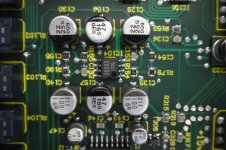
As an aside I have just seen something odd, a surface mounted capacitor placed on the board with what appears to be reversed polarity. As I have owned this from new that is how it left the factory and it worked fine for years. I thought that a reversed cap would have exploded? Please see photo attached.
A few years ago one channel started to emit an unpleasant hum shortly after being switched on. It sounded like a wave and occured even with the volume turned all the way down. I tried simple things like swapping cables, speakers etc but to no avail and concluded that the pre was just faulty. Headphone output worked fine. Repair from Cyrus was uneconomical and I could find very little information about undertaking a bit of simple DIY. A couple of capaciors measured below tolerance so I replaced these just because I could, it made no difference.
I stored it and on switching on recently, it powers up but then goes into standby and fails to come out of that. My skill level with electronics is low, I can solder safely and successfully, can use a multi-meter and understand that pratting around with anything live is potentially deadly. I do however wonder about using the casework and perhaps some of the controls to build a passive pre-amp and wondered if this a viable project? Indeed if anyone has tried this with this particular preamp and could direct me to further reading.
As an aside I have just seen something odd, a surface mounted capacitor placed on the board with what appears to be reversed polarity. As I have owned this from new that is how it left the factory and it worked fine for years. I thought that a reversed cap would have exploded? Please see photo attached.
Attachments
A passive preamp is no preamp at all. It's simply a potentiometer arranged to attenuate the signal from the source before it's connected to the power amplifier. That seems OK so far, but there can be issues with the source impedance that is a mismatch to the pot. or the pot output impedance input is mismatched to the power amplifier input.
re: your pic.
Not sure where these caps are located but some appear to be associated with dual OPAMP IC104, a 5532 type and some at least will be connected to its +/-15V supplies and ground. C129,130 do appear reversed but assuming you can make contact with the the copper tracks to the capacitor solder pads, a quick check with power on and a multimeter will soon tell you whether the polarity marks on the board or the cap orientation are in error.
It's also possible that electrolytic caps may have been reversed to suit circuit voltages that were not expected at the design phase. That's often the case where Electrolytic caps are used as DC blocking caps for the signal.
Thanks Ian, I take your point about the pre-amp, it echoes what I have already learned about potential mismatching so will not devote any further energy to pursuing. I was just a bit curious about how I might make some use of this unit rather than stick it back in a cupboard.
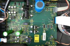
For info only I have attached a photo of the main board just to give context to my original posting and in case anyone might be interested.
For info only I have attached a photo of the main board just to give context to my original posting and in case anyone might be interested.
Attachments
There is solutions to building a totally new preamplifer circuit and installing one instead of the original pcb. Everything about this enclosure, connectors, switches, buttons etc. is worth keeping. Go to a subforum "Analog Line Level" and ask for further advice.
If it were me, I'd use a service manual from a reputable manufacturer and duplicate a line level preamp.
If it were me, I'd use a service manual from a reputable manufacturer and duplicate a line level preamp.