My Maplin Millenium clone didn't work so I'm going to salvage the expensive components for this Williamson 5-20.
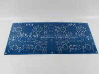
It uses an E-Bay PCB from R-Sound.
I'm salvaging the following components:-
4 x EL34, 2 x EF86, 2 x ECC83
2 x Hammond 1650H 6.6K OPTs
240V / 350V 250VA transformer (actually 2 transformers working together)
240V / 6V 50VA transformer
The B+ might be a bit high. I'm aiming to reduce it with a CRC arrangement. Solid State rectification into 220uF then 200R followed by 600uF.
Attachments
Last edited:
The 5-10 & 5-20 were Mullard designs. Williamson was a different design. You are in the land they both originated, Her Majesties Kingdom of UK, Which anp is it?😕
I haven't got the schematics for the boards yet so I might need to make a few design choices later.
This is the Williamson
I think it is better to call it at best some variant of the Williamson, as there would need to be significant changes to gain structures and frequency response, as all the main parts have different specs.
The Williamson audio power amplifier circuit has now been "adapted to death" since its original publication in the pages of WW in the later 40,s.
I have the original issue of WW which would be much different to later "non-Williamson " original designed .
Which version of the modified design are you after --the USA has a 60 watt version using 6550,s .
What people don't realise not studying original histories of old design audio amplifiers is the Williamson himself specified special transformers for his design---JLH commented on this in the pages of EW .
I myself would admit to using JLH designs but heavily modified in various versions but I would not say --- its JLH,s "original design " .
One of the main reasons the original was somewhat stable with NFB was the output section was triode wired. Soon many were trying pentodes & wondered why the circuit flew into orbit while driving a loudspeaker load.
Even now many amateurs don't know that the gain of pentodes follows the load impedance, something that can vary a lot. So if NFB was set while on a load resister it will be a lot more at some frequencies on a loudspeaker load.
The Williamson also has low frequency instability sometimes causing the loudspeaker to 'breath'. Too much gain & too much phase shift, instability is a sure thing.🙂
Like all things 'Williamson', if the original design parts are not used then caveat emptor - that goes for instability observed in clones/variants at LF and HF ends. In the original, the designed OPT LF resonance was pushed sufficiently low in frequency, helped by the choice of KT66.
Any generalisation of instability was typically remarked by those who made changes and got caught out. Not that making changes is bad, just that other remedial changes are often needed to allow stability. Many such remarks appeared in magazine articles, and were often a way for authors to grandstand their supposed improvements, but the baseline was that they often couldn't or wouldn't use parts appropriate to the original design.
Any generalisation of instability was typically remarked by those who made changes and got caught out. Not that making changes is bad, just that other remedial changes are often needed to allow stability. Many such remarks appeared in magazine articles, and were often a way for authors to grandstand their supposed improvements, but the baseline was that they often couldn't or wouldn't use parts appropriate to the original design.
The lessons learned back in those days seem to have been somewhat lost since. How often do we see new constructors post "I built this XYZ amplifier from a schematic and only changed the output transformers and used larger coupling caps because I read on my guru's webpage that's better. Why doesn't it work?"
Everything old is new again.
Chris
Everything old is new again.
Chris
There have been OPT/tube combinations that I’ve never been able to get stable in a Williamson, despite throwing every technique in the book at them. I ended up giving up on some 7591’s with some 25 watt 10k ohm iron I “found”. The same iron and front end are perfectly stable with triode strapped EL 34’s (less gain, lower Rout).. I had some EL84’s and cheap iron give me equal fits - again, changing the topology ultimately. Where I spent the money on good iron, on my 200 watters, I got it stable (and no LF ringing) even with no load at full drive. Good iron seems to be a necessity - you don’t want that low frequency pole to be ill-defined or the math becomes chaos theory. I needed to apply some LF phase compensation to get it that clean - although it never “took off” without it.
The Mullard 5-20 amplifier used an EF86 as the input voltage amplifier, into a 12AX7/ECC83 long-tailed pair, driving push-pull EL34s. As described here:
Twenty-Watt Amplifier
The Williamson Amplifier in its more modern form used a 6SN7 as an input voltage amplifier into a cathodyne (split load) phase splitter, into a second 6SN7 differential driver stage, driving a push-pull pair of KT66, 6L6 or similar -- although EL34, KT88, 6550 output tubes were used later by others such as Keroes and Hafler of Acrosound --
acro.
--
As I said earlier, I haven't got the schematics yet so this is a bit of guess work.
The PCB uses B9A sockets for the phase splitter and the input amp. I'm guessing these will be the EF86 and ECC83 as the 6SN7 is an octal.
The PCB uses B9A sockets for the phase splitter and the input amp. I'm guessing these will be the EF86 and ECC83 as the 6SN7 is an octal.
This design appears to use two 12AU7 or a whole raft of other dual triodes. There is no schematic on the eBay page unfortunately but the built images give some clues.
Williamson push-pull Amplifier circuit board For 12AX7/12AU7/EL34/KT88/6P3/6L6 | eBay
Some slightly different pictures in this listing.
Williamson push-pull Amplifier circuit board For 12AX7/12AU7/EL34/KT88/6P3/6L6 | eBay
Williamson push-pull Amplifier circuit board For 12AX7/12AU7/EL34/KT88/6P3/6L6 | eBay
Some slightly different pictures in this listing.
Williamson push-pull Amplifier circuit board For 12AX7/12AU7/EL34/KT88/6P3/6L6 | eBay
Thats the general problem with amateur DIY. They change, alter, swap everything without a deeper understanding. In the end, the majority of DIY schemos on the web have big design errors, most often false dimensioning and the rules for good amp design aren't known.
A circuit that old, with the original parts no longer available and dozens of modded incarnations on the web is just an example.
I studied those DIY tube world for quite some years but what I stored are just the pro- designs of good brand and names. Anything other is mostly crap, has design errors, is altered for no or the wrong reasons etc. This leads directly to audio hell.
- Home
- Amplifiers
- Tubes / Valves
- New Williamson 5-20 40W Build