I really like stabilised B+ for everything i build.
Ive allready done maida-style regulators with a tube as a pass element, and i have used current source loaded EF184's for control of the tube.. Both gave excelent results.
I was looking at the denoizer for the 317 found in this thread https://www.diyaudio.com/forums/pow...canceller-retrofit-upgrade-317-based-reg.html
and i figured, what if i combine all these ideas into one?
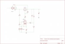
I figured i could CCS load the pentode with the adjust pin of the 317 and run the 317 as cascode with the pass tube.
Im curious as to what people think of this..
Ive allready done maida-style regulators with a tube as a pass element, and i have used current source loaded EF184's for control of the tube.. Both gave excelent results.
I was looking at the denoizer for the 317 found in this thread https://www.diyaudio.com/forums/pow...canceller-retrofit-upgrade-317-based-reg.html
and i figured, what if i combine all these ideas into one?
I figured i could CCS load the pentode with the adjust pin of the 317 and run the 317 as cascode with the pass tube.
Im curious as to what people think of this..
Attachments
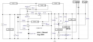
The LM supplies only the bias for the passer tube. This cct also flies well with an NFET in the cathode of the passer. Not new tho, see attached. Looks like my copy needs another scan, this one done in the distant past.🙂
Too much capacity at the output terminals could cause this cct to oscillate.
Too much capacity at the output terminals could cause this cct to oscillate.
Attachments
-
 Philips PS I.jpg634.6 KB · Views: 92
 -
 Philips PS H.jpg467.6 KB · Views: 104
 -
 Philips PS G.jpg500.7 KB · Views: 97
 -
 Philips PS F.jpg623.4 KB · Views: 71
 -
 Philips PS E.jpg604.9 KB · Views: 65
 -
 Philips PS D.jpg603.7 KB · Views: 197
 -
 Philips PS C.jpg622.2 KB · Views: 207
 -
 Philips PS B.jpg550.8 KB · Views: 209
 -
 Philips PS A.jpg509.1 KB · Views: 217
 -
 Philips PS J.jpg568.6 KB · Views: 75
I always wondered about using an 811a as a pass device because of the high mu and low grid voltage. High grid current could be a problem though. It would certainly handle faults more gracefully than a mosfet.
This will work
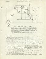
Using a higher mu passer. The sim is kinda busy with many parts while looking at performance. In the end I never built one, another contract came along to keep me running five more years.🙂
Using a higher mu passer. The sim is kinda busy with many parts while looking at performance. In the end I never built one, another contract came along to keep me running five more years.🙂
Attachments
I don't think I see anything to ensure the 317 only has 60V or less across it.
Yeah, if for some reason the tube shorts internally, or the cathode starts flaking that 317 is a goner as well.
I figured you could use the 317HV because i think it is slightly more stable than the TL783 with its N-mos pass element. But this is purely unsubstantiated.
One of the reasons i chose the adjust resistor at 10mA is to make sure that the 317 pass transistor doesnt start zenering at no load current. otherwise the 3mA or so you'd normally set the divider of the 317 would have sufficed.
Using a higher mu passer. The sim is kinda busy with many parts while looking at performance. In the end I never built one, another contract came along to keep me running five more years.🙂
What are the 100 ohm resistors in the cathode lead used for? my guess they are used to force the tubes to share current, and at the same time swamp the difference in output impedance of the cathode followers due to variations in GM.
You are on the money. By putting the equalizing resisters in the cathodes they are (mu + 1) times as effective forcing current sharing than there are if put on the plate side.
What about the IRF840 is that just something you had laying around? or should i get a lower miller/higher early voltage part to increase gain and bandwidth?
Edit, i take it the 100mOhm is there for the same reason? Local feedback?
Edit, i take it the 100mOhm is there for the same reason? Local feedback?
I always wondered about using an 811a as a pass device because of the high mu and low grid voltage. High grid current could be a problem though. It would certainly handle faults more gracefully than a mosfet.
There are some mosfets that have some insane SOA capabilities. Like the IXTK8N150L
My problem with mosfets is not really the SOA. but insulation requirements and drive requirements. Miller is also much much higher in mosfets than tubes, so you need a low Zout driver i think.
Furthermore another consideration is weight, a 50W tube weighs less than a heatsink that can dissipate 50W. Because of the difference in convection cooling and radiation cooling.
As far as i know, there are two ways of going about doing a linear mosfet regulator. One is to take an opamp, and compensate it for the capacitive load. T-Reg by Jan Didden is one example.
The other is to just shield the opamp from all the nasty capacitances with a buffer. E.G. LH0002
The all tube regulator is pretty good and "bulletproof" , you must have a very good reason to mix them with semiconductors
Yeah. I do. I want to beat the 0.3mV RMS noise figure of my last tube regulator.
I didn't get there with a tube/maida regulator.
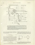
If you look at a EF184 closely, you will realize this tube alone has 4K gain or so if you load it with a high impedance current source. I realized this after reading about the Phillbrick tube opamps that mentioned in passing that the designers wanted to use pentodes with current source anode loads, but no practical way for current source anode load was available at the time.
Heres a Dutch forum post i did on that circuit at the time : Geregelde buizenvoeding - Forum - Circuits Online
I didn't get there with a tube/maida regulator.
If you look at a EF184 closely, you will realize this tube alone has 4K gain or so if you load it with a high impedance current source. I realized this after reading about the Phillbrick tube opamps that mentioned in passing that the designers wanted to use pentodes with current source anode loads, but no practical way for current source anode load was available at the time.
Heres a Dutch forum post i did on that circuit at the time : Geregelde buizenvoeding - Forum - Circuits Online
- Home
- Amplifiers
- Tubes / Valves
- Kinda interesting tube regulator idea.