Hi all,
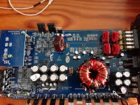
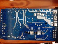
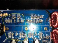
I have this 5 channel amplifier, it doesn't power on, stuck in protect. All psu fets are not shorted. it has 2 ics, not sure how I can test or identify these. one of the ic's has a discoloration.
I have this 5 channel amplifier, it doesn't power on, stuck in protect. All psu fets are not shorted. it has 2 ics, not sure how I can test or identify these. one of the ic's has a discoloration.
Attachments
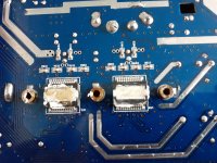
Those 2 ICs are for your output. they could be either TDA8954 OR TDA8920. Clean up the silicone grease and you will be able to the correct number.
It looks like there may have been some contamination on one IC. If something burns, it's generally a black that's produced.
These are likely TDA8954 ICs (attached). If so, you can start by testing for shorts between the center legs of each of the rectifiers (assuming that the rectifiers aren't doublers) and each of the speaker terminals.
These are likely TDA8954 ICs (attached). If so, you can start by testing for shorts between the center legs of each of the rectifiers (assuming that the rectifiers aren't doublers) and each of the speaker terminals.
Attachments
Those 2 ICs are for your output. they could be either TDA8954 OR TDA8920. Clean up the silicone grease and you will be able to the correct number.
Cleaned up the grease, no markings on it
It looks like there may have been some contamination on one IC. If something burns, it's generally a black that's produced.
These are likely TDA8954 ICs (attached). If so, you can start by testing for shorts between the center legs of each of the rectifiers (assuming that the rectifiers aren't doublers) and each of the speaker terminals.
I tested between the centre legs of the rectifiers and speaker terminals, there are no shorts
You stated that there were no shorted PS FETs. What about the FETs for the sub channel?
The number is on the other side, etched in the plastic.
The number is on the other side, etched in the plastic.
Is the power supply trying to power up for long enough to tell if it's producing ± rail and regulated voltages?
What's the DC resistance between the B+ terminal and the secondary ground?
What's the DC resistance between the B+ terminal and the secondary ground?
Last edited:
Only positive 29?
What about the regulated voltages and the resistance from B+ to secondary ground?
What about the regulated voltages and the resistance from B+ to secondary ground?
All rail voltages are present.
resistance between B+ to secondary ground is 2 mega ohm
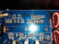
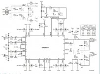
I removed the ics (TDF8591TH) and the amp powers on. There seems to be some caps that are out of tolerance in below circuit.
C13A, C14A, C15A, C16A are meant to be 100nf or 20nf?
resistance between B+ to secondary ground is 2 mega ohm
I removed the ics (TDF8591TH) and the amp powers on. There seems to be some caps that are out of tolerance in below circuit.
C13A, C14A, C15A, C16A are meant to be 100nf or 20nf?
Attachments
Reinstall one IC at a time to see if one of the ICs (or possibly one IC location) is causing the problem.
Does IC A cause a problem in either location?
I don't see any burned resistors so the values on the resistors should be used. If you find that the amp designer used the reference design provided by the IC manufacturer, the diagram may be useful for unmarked capacitors.
I don't see any burned resistors so the values on the resistors should be used. If you find that the amp designer used the reference design provided by the IC manufacturer, the diagram may be useful for unmarked capacitors.
- Home
- General Interest
- Car Audio
- Energy Audio 5 channel in protect