I'm working on an all-mosfet amplifier where I'd like to run the front end ten (or more) volts higher than the output stage, so it can drive the output stage rail-to-rail.
I noticed that my benchtop lab supply is configured as two floating supplies that can be connected in series, so I was wondering, could the same thing be done with a small PCB-mounted transformer, to boost the main supply by ten volts or so for the front end?
Here's an example of what I have in mind. A pair of floating 10V low current supplies are "stacked" above/below the main power supply rails for the output stage.

Another option would be connecting the secondaries in series, sort of like having an extra set of taps on the main transformer. I saw this configuration (extra taps on the main transformer) used on some Adcom GFA-5XXX MOSFET amplifiers to boost the front end, with ten ohm resistors between the secondaries (presumably for a good reason, but I'm not quite sure what their purpose is).

Finally, on the Adcom GFA-5800, I saw an example of stacked supplies with two transformers in a rather unusual configuration: the primary of the transformer that boosts the voltage for the front-end is connected to the secondary of the main transformer for the output stage. I've been puzzling over what benefit this might provide, but the answer eludes me (maybe the turns ratio just worked out and it was most economical?).

I would be interested in any pros or cons for these different options. Maybe the whole thing is a dumb idea? This would be going on an AB amp, so the main supply might have some voltage fluctuation. Regulating the front end is also an option, but my main goal is to keep it simple and easy to understand, so I would like to avoid that.
I noticed that my benchtop lab supply is configured as two floating supplies that can be connected in series, so I was wondering, could the same thing be done with a small PCB-mounted transformer, to boost the main supply by ten volts or so for the front end?
Here's an example of what I have in mind. A pair of floating 10V low current supplies are "stacked" above/below the main power supply rails for the output stage.
Another option would be connecting the secondaries in series, sort of like having an extra set of taps on the main transformer. I saw this configuration (extra taps on the main transformer) used on some Adcom GFA-5XXX MOSFET amplifiers to boost the front end, with ten ohm resistors between the secondaries (presumably for a good reason, but I'm not quite sure what their purpose is).
Finally, on the Adcom GFA-5800, I saw an example of stacked supplies with two transformers in a rather unusual configuration: the primary of the transformer that boosts the voltage for the front-end is connected to the secondary of the main transformer for the output stage. I've been puzzling over what benefit this might provide, but the answer eludes me (maybe the turns ratio just worked out and it was most economical?).
I would be interested in any pros or cons for these different options. Maybe the whole thing is a dumb idea? This would be going on an AB amp, so the main supply might have some voltage fluctuation. Regulating the front end is also an option, but my main goal is to keep it simple and easy to understand, so I would like to avoid that.
I have not done this with stacked transformers but have used a mosfet regulator to create the voltage differential between the driver stage and output stage . I like your idea of stacking transformers as it negates the hassle and risk of high current regulation.
..dB
..dB
Hello, Rory Christ
I also considered using "Stacked Power Supplies", but some netizens reported that when it was used in this way, the THD+N data deteriorated, and then he cancelled Stacked Power Supplies.
I don’t remember where I saw the response. I am very interested in the real result. Will I encounter additional problems if I do this?
If the bottom of the "stack" is the power stage power supply, My guess is that high current draw on this power supply will modulate the stacked input stage power supply unless you do some regulation and throw away some of those extra volts that you are stacking.
Splitting the front end and output stage rails is a good thing to do!
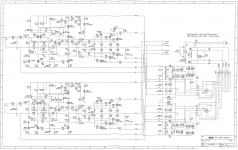
But if you're taking all the trouble of adding another transformer, then make it do the whole 50-55V instead of just riding on top of the output stage PS taps (see Adcom 5400 attached).
I suggest adding an extra 5V to lose in a fat CLC in the front end PS, like I did recently:
https://www.diyaudio.com/forums/pass-labs/361693-ps-hack-adcom-gfa-5400-a.html#post6378414
On later Adcom 5200, they changed the PS from shared rails to separate rails, and I have one of each amp, and the separate rails version is obviously cleaner.
https://www.diyaudio.com/forums/pas...fier-1995-adcom-gfa-5200-a-9.html#post6459134
Attachments
I agree with Andersonix. If you have a second transformer, there's no need to stack. Get the lower power transformer with a higher secondary voltage. Get it plenty high, and use a linear regulator to get to the desired voltage.
Probably the reasons people stack with separate transformers are
1) Simplifies the AC mains protection.
2) Provides the desired power supply sequencing they want.
1) is not really a big deal, I think, and 2) should be automatic. You want the input circuits to come to voltage first, and the output stage to power up second. Tens of thousands of uF on the output stage supply, and inrush current limiting will easily ensure that happens.
Forgive me if I missed it, but the Circuit topology may play a part in the decision.
Having a separate power supply for the front end is desirable in transformer or cap coupled stages. It can risk bias shifts in DC coupled stages.
The stacked supplies may be less affected than truly separate supplies, but it is something to consider.
Good luck with your project.
Having a separate power supply for the front end is desirable in transformer or cap coupled stages. It can risk bias shifts in DC coupled stages.
The stacked supplies may be less affected than truly separate supplies, but it is something to consider.
Good luck with your project.
Having a separate power supply for the front end is desirable in transformer or cap coupled stages. It can risk bias shifts in DC coupled stages.
Doug, could you elaborate on how a separate front end supply could result in bias shifts?
The amplifier I'm working on is similar to the Adcom schematic posted above (three stage, all mosfet).
I played around with this in the simulator, and it seemed like the bias current was mostly a function of the output stage rails, not the front end voltage. If I dropped the output stage voltage by five volts, the bias was pretty much the same regardless of whether the front end was also lowered by five volts, or kept unchanged.
I agree with the sentiment that the ideal situation is to have a completely separate power supply for the front end.
One of the reasons I'm looking at this is that it is easy to find low voltage transformers, but the selection of high voltage, low current transformers is somewhat limited.
So, this is more an exercise of "how could I design this with easily obtainable parts", rather than "what is the ultimate power supply design". It is also fun to explore something a little off the beaten path and learn some things along the way.
Probably there's not enough room to add the 10V worth of extra windings onto the typical torroidal transformer, but with small enough wire it might get there?
I agree with you Rory. If the PSU for the output stage is dead, then the output transistors and speakers are safe. The output PSU can then ramp up while the input stage controls the loop. You have already designed for the output PSU to be 5 to 10 V lower than the input PSU, so it won't hurt for the output PSU to be much lower for a few tens of ms.
How's this going, Rory?The amplifier I'm working on is similar to the Adcom schematic posted above (three stage, all mosfet).
The stock Adcom 5400 has front end rails 12.5VDC higher than output stage...
- Home
- Amplifiers
- Pass Labs
- Stacked Power Supplies