under
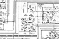
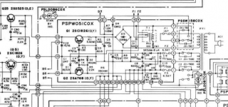
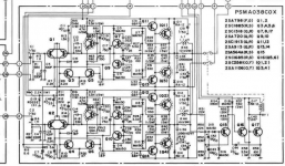
Cybernet SRC-80 Service
unfortunately there are all pages include the schematic filed in jpg and not the usually used pdf.
In the attachment I try to get the schematic more dark for better reading.
But maybe one of the members have it in PDF and higher resolution.
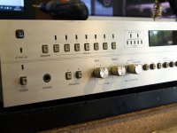
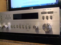
Cybernet (Kraus) SRC-80 & SCD-80
Cybernet SRC-80 Service
unfortunately there are all pages include the schematic filed in jpg and not the usually used pdf.
In the attachment I try to get the schematic more dark for better reading.
But maybe one of the members have it in PDF and higher resolution.
Cybernet (Kraus) SRC-80 & SCD-80
Attachments
-
 QPfy1l3h.jpg118.6 KB · Views: 305
 -
 DSCF9425.jpg560.8 KB · Views: 157
 -
 DSCF9424.jpg590.5 KB · Views: 160
 -
 wfUa4qah.jpg93.5 KB · Views: 197
 -
 DSCF9417.jpg761.6 KB · Views: 197
 -
 wS0GOPOh.jpg115.2 KB · Views: 206
 -
 SLgKYOdh.jpg167.8 KB · Views: 226
 -
 r766HtKh.jpg125.1 KB · Views: 235
 -
 Mw7pkwYh.jpg198.3 KB · Views: 271
 -
 Cybernet SRC-80 Service Manual-29-dunkel.jpg1.1 MB · Views: 285
Last edited:
After upload here the resolution of schematic seems to be better.
Attachments
-
 wS0GOPOh.jpg115.2 KB · Views: 108
 -
 pGtScGAh.jpg143.3 KB · Views: 114
 -
 Cybernet SRC-80 Service Manual-Voltage-Reg.png525.8 KB · Views: 141
 -
 Cybernet SRC-80 Service Manual-Switch-On.png420.6 KB · Views: 239
 -
 Cybernet SRC-80 Service Manual-Power Amp.png607.7 KB · Views: 222
 -
 img_20200425_103108.jpg75.1 KB · Views: 121
 -
 img_20200425_103101.jpg67.6 KB · Views: 104
 -
 ee75e48d256b.jpg63.3 KB · Views: 108
 -
 d8aa2fd60e40.jpg54.9 KB · Views: 116
 -
 c52393af691d.jpg57.4 KB · Views: 106
Last edited:
Thank you very much.
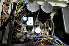
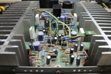
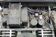
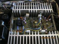
Curious at first glance is the fact, that the on/off switch isn't a main switch, because only secondary winding of the mains transformer are switched (transformer is always in "ON" mode).
But after a closer look I discover the absence of a battery pack resp gold cap to back up the saved radio stations.
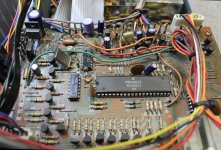
Consequence of this are burned switch contacts, which I have shorted. After this and elimination of various contact issues on the source selector switches and attenuator pot this stereo receiver works without trouble (switch on and switch off takes place on an outdoor power strip).
How I can realize an upgrade with a charger and a rechargeable 3V6 battery pack (e. g. 3 pcs. 1V2 micro).
Thank you for upload a link for such a project.
Curious at first glance is the fact, that the on/off switch isn't a main switch, because only secondary winding of the mains transformer are switched (transformer is always in "ON" mode).
But after a closer look I discover the absence of a battery pack resp gold cap to back up the saved radio stations.
Consequence of this are burned switch contacts, which I have shorted. After this and elimination of various contact issues on the source selector switches and attenuator pot this stereo receiver works without trouble (switch on and switch off takes place on an outdoor power strip).
How I can realize an upgrade with a charger and a rechargeable 3V6 battery pack (e. g. 3 pcs. 1V2 micro).
Thank you for upload a link for such a project.