Can anyone explain this to me? It's probably a really dumb question!
The schematic shows the motor drive for the Thorens TD320 turntable. the motor is 16V AC. The power supply is single ended 18V.
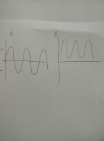
My question is this. The supply to the motor needs to be as in diag A, so going from + to - does it not? But if the power supply is +18V the supply to the motor will be like in diag B. In which case, how does that run the motor?
The schematic shows the motor drive for the Thorens TD320 turntable. the motor is 16V AC. The power supply is single ended 18V.
My question is this. The supply to the motor needs to be as in diag A, so going from + to - does it not? But if the power supply is +18V the supply to the motor will be like in diag B. In which case, how does that run the motor?
Attachments
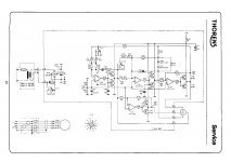
The motor is a 3 phase motor and gets power from Z101. The first part controls the oscillator speed where the three other op amps control the three phases. Phase offset is acheived by RC timing from the oscillator.
Thanks for your reply.
It's a 2-phase motor, I believe.
I'm wondering not about phase but how the AC output swings from + to - if the power supply is +18V.
It's a 2-phase motor, I believe.
I'm wondering not about phase but how the AC output swings from + to - if the power supply is +18V.
The drive board for the TD320 is a Quadrature oscillator with a zener agc which then feeds 2 H-bridge amplifiers to supply the 2 motor windings.
The transistors in the H-bridge are TO92 packages. R110 and R119 bias the opamp.
This is similar to the Phonosophie No.3
https://www.diyaudio.com/forums/ana...uit-diy-turntable-project-10.html#post3431519
The transistors in the H-bridge are TO92 packages. R110 and R119 bias the opamp.
This is similar to the Phonosophie No.3
https://www.diyaudio.com/forums/ana...uit-diy-turntable-project-10.html#post3431519
Last edited:
Your picture A assumes one side of a motor winding is grounded. However this circuit drives both sides of each motor winding in the range 0->18v, so we can have the case where:
- side_A = 17v, side_B = 1v => voltage AB = 17-1 = +16v
- side_A = 1v, side_B = 17v => voltage AB = 1-17 = -16v
Hope that helps!
- side_A = 17v, side_B = 1v => voltage AB = 17-1 = +16v
- side_A = 1v, side_B = 17v => voltage AB = 1-17 = -16v
Hope that helps!
It seems to be the PS800, I have one from a TD850, it is not very accurate in frequency nor stable.
Oh really? I've had several TD300 series over the years and I've found the speeds very stable. I currently run a TD520 which has a built-in strobe and the speeds are solid as a rock. It has essentially the same drive circuit as the 300 series.
Its an RC oscillator at heart, so definitely nothing like as stable as ac mains or a quartz-derived signal, doesn't mean its not good for the job though.
The drive board for the TD320 is a Quadrature oscillator with a zener agc which then feeds 2 H-bridge amplifiers to supply the 2 motor windings.
The transistors in the H-bridge are TO92 packages. R110 and R119 bias the opamp.
This is similar to the Phonosophie No.3
https://www.diyaudio.com/forums/ana...uit-diy-turntable-project-10.html#post3431519
I realise the circuit contains an RC oscillator . However I am a bit puzzled - it seems to most closely resemble a quadrature oscillator using the two top left op amps. However a quadrature oscillator requires 3 RC segments whereas this only appears to have 2 ( consisting of the 1% toleranced caps and resistors, I assume). I'm obviously missing something here!
...However a quadrature oscillator requires 3 RC segments whereas this only appears to have 2 ....
I agree. 2 can work only at infinity. In practice two obvious poles won't sing, but one more much higher pole will bring it to the sing point, but with poor control of frequency.
The Quadrature Oscillator
https://backend.orbit.dtu.dk/ws/portalfiles/portal/4572799/ecctd09-A4P-F4-9047p.pdf
It is always possible the drawing is incomplete. Or that the amplitude control (Zener thing) hides a pole.
I realise the circuit contains an RC oscillator . However I am a bit puzzled - it seems to most closely resemble a quadrature oscillator using the two top left op amps. However a quadrature oscillator requires 3 RC segments whereas this only appears to have 2 ( consisting of the 1% toleranced caps and resistors, I assume). I'm obviously missing something here!
Sorry my mistake.
I've notice the TD320 circuit is different to the Phonosophie.
The TD320 oscillator is more like a State Variable Filter Oscillator.
ESP - Sinewaves
- Home
- Source & Line
- Analogue Source
- AC motor drive from single-ended supply