I realize that Sota doesn’t publish schematics and such and given that, it may be tough to help me, but trying anyway. . .
A friend just picked up a Sota Sapphire II with a Series IV or V upgraded motor. The seller had cobbled together a power supply using a HP computer wall wart, which worked okay.
But the cobbled part came uncobbled and the lightly soldered connections between the 30V DC wall wart wires and the wires going to the Sota motor board got reversed (!!) and a puff of smoke resulted. Reversed the wires the way they should have been and tried again, and another puff of smoke appeared.
So the questions:
- Is the motor itself likely still okay?
- What component/s are most likely to have been blown by that initial 30v reverse voltage?
I’m going to try and help him repair the motor board, and we’re willing to go down the brute force shotgun path of replacing every component if needed (and probably will do all the electrolytic caps in any case since they look original), but if someone can point to the most likely components to be blown in a reverse bias scenario, that would be very helpful.
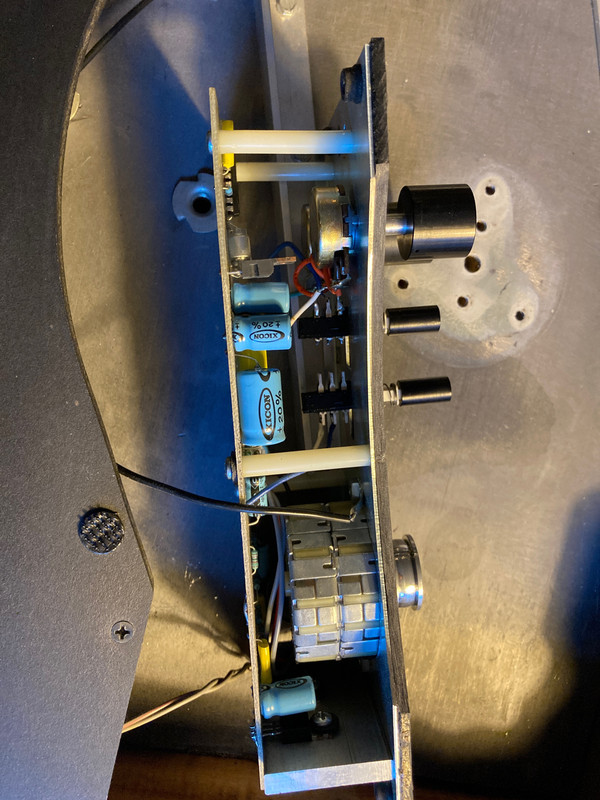
Couple of pics attached so I’m not making any faulty assumptions on what motor we’re dealing with here.
A friend just picked up a Sota Sapphire II with a Series IV or V upgraded motor. The seller had cobbled together a power supply using a HP computer wall wart, which worked okay.
But the cobbled part came uncobbled and the lightly soldered connections between the 30V DC wall wart wires and the wires going to the Sota motor board got reversed (!!) and a puff of smoke resulted. Reversed the wires the way they should have been and tried again, and another puff of smoke appeared.
So the questions:
- Is the motor itself likely still okay?
- What component/s are most likely to have been blown by that initial 30v reverse voltage?
I’m going to try and help him repair the motor board, and we’re willing to go down the brute force shotgun path of replacing every component if needed (and probably will do all the electrolytic caps in any case since they look original), but if someone can point to the most likely components to be blown in a reverse bias scenario, that would be very helpful.
Couple of pics attached so I’m not making any faulty assumptions on what motor we’re dealing with here.
If you can separate the board from the assembly and get a decent photo of each side it should be feasible to recreate the circuit diagram, especially if you identify any part numbers.
It would also be useful, if possible, to identify where the smoke came from 🙂
It would also be useful, if possible, to identify where the smoke came from 🙂
Thanks. My friend is likely bringing over the board today. I’ll disassemble and try to trace out a schematic with part #’s. Will post back when I do.
Since polarity was reversed I would replace all electrolytic caps, they look old anyway, and then test all semiconductors, replacing those that are obviously blown and also the ones that are available and cheap, just to be safe. Resistors- look for heat damage, measure all of them, replacing where necessary. The board looks like it is a very basic circuit, not too many parts, so unless they used unique or NLA parts that can’t be substituted, the whole rebuild should not put too much of a dent in your friend’s bank account.
Oh- also make certain that the wall wart used is putting out the correct voltage required by the circuit. Too high and it might overheat.
Oh- also make certain that the wall wart used is putting out the correct voltage required by the circuit. Too high and it might overheat.
Since polarity was reversed I would replace all electrolytic caps, they look old anyway, and then test all semiconductors, replacing those that are obviously blown and also the ones that are available and cheap, just to be safe. Resistors- look for heat damage, measure all of them, replacing where necessary. The board looks like it is a very basic circuit, not too many parts, so unless they used unique or NLA parts that can’t be substituted, the whole rebuild should not put too much of a dent in your friend’s bank account.
Oh- also make certain that the wall wart used is putting out the correct voltage required by the circuit. Too high and it might overheat.
Thanks. There are 4 IC’s I can see. Two voltage regulators (one 12V and one 24V). The 24V is shorted input to output, the 12V is not, but I’ve ordered replacements for both as well as all electrolytic caps. There are some film caps - haven’t measured those yet, but I will try with my cap meter.
The other two IC’s are a waveform generator (about $10) and a dual opamp/power amp (Allegro ULN3755W in SIP12 package), which per Mouser is obsolete and no modern sub. I can buy one off eBay for $50.
So I’m going to hold off on those two ICs for now and see if new voltage regulators and caps fixes this. I don’t know an easy way (for me) to test those two ICs.
I measured some resistors, but not all. That’s today’s task. I think they’ll be okay, but will make sure.
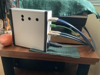
The wall wart is putting out 30V, which I’m told is the correct voltage. I just need to make the connection from wall wart to Sota more robust. My friend and I were discussing various options. May go with female RCA’s (one for positive and one for negative) from wall wart side (so voltage is not exposed on active side) to mate with male RCA connectors on TT side. So the power connect will be detachable (the wall wart is quite big and heavy).
If I were certain that the insulation of a RCA cord were sufficient to insulate a 30V differential in a single cable I could do that too, but I don’t know that to be the case and it seems like it might leave open the possibility of a short developing if the cord got nicked - more so than if +/- were carried to different cables each with more robust insulation.
I’ll update once voltage regs and caps are replaced and board is fired up.
Thanks. There are 4 IC’s I can see. Two voltage regulators (one 12V and one 24V). The 24V is shorted input to output, the 12V is not, but I’ve ordered replacements for both as well as all electrolytic caps. There are some film caps - haven’t measured those yet, but I will try with my cap meter.
The other two IC’s are a waveform generator (about $10) and a dual opamp/power amp (Allegro ULN3755W in SIP12 package), which per Mouser is obsolete and no modern sub. I can buy one off eBay for $50.
So I’m going to hold off on those two ICs for now and see if new voltage regulators and caps fixes this. I don’t know an easy way (for me) to test those two ICs.
I measured some resistors, but not all. That’s today’s task. I think they’ll be okay, but will make sure.
The wall wart is putting out 30V, which I’m told is the correct voltage. I just need to make the connection from wall wart to Sota more robust. My friend and I were discussing various options. May go with female RCA’s (one for positive and one for negative) from wall wart side (so voltage is not exposed on active side) to mate with male RCA connectors on TT side. So the power connect will be detachable (the wall wart is quite big and heavy).
If I were certain that the insulation of a RCA cord were sufficient to insulate a 30V differential in a single cable I could do that too, but I don’t know that to be the case and it seems like it might leave open the possibility of a short developing if the cord got nicked - more so than if +/- were carried to different cables each with more robust insulation.
I’ll update once voltage regs and caps are replaced and board is fired up.
One open question about the RCA power connect though is whether the signal line of a RCA is of sufficient gauge to carry the amps/power needed for the motor circuit. Since they typically only carry a low power, low voltage signal.
If that’s questionable, I can buy more traditional 2.1/5.5mm power jack connectors and use thicker wire than what a RCA cable might use.
Thoughts?
I wouldn't use an RCA plug for any kind of power connector, there's too much chance of a mishap somewhere down the road. I would use a DC power connector, preferably not one of a size commonly used for 5v or 12V
I wouldn't use an RCA plug for any kind of power connector, there's too much chance of a mishap somewhere down the road. I would use a DC power connector, preferably not one of a size commonly used for 5v or 12V
With regards to RCA, are you concerned about the technical capability of an RCA to carry power, or the potential for confusion down the road (someone plugging one side or another into somewhere they shouldn’t due to connector type)?
Same question on 5v/12v connectors - for technical reasons or to avoid mishap due to confusion?
Do you have any particular suggestions for a good 30V DC power connector?
Thank you.
On a recent phono preamp build I used a 5 pin xlr jack/plug to carry the power to the preamp from an external box with the transformer/rectifier and bulk filter caps. These connectors are not expensive, are very reliable and robust, lock in place and are commonly available. Those little DC barrel connectors just seem like a problem waiting to happen. I’ve seen too many of them develope bad connections as they age. I see Parts Connexion is offering gold plated versions of the barrel connectors but they are more expensive then the xlr’s. The xlr takes up more space and is harder to install if those are issues.
Edit- The ones in the photo are Neutrik brand- worth the small extra cost IME.
Edit- The ones in the photo are Neutrik brand- worth the small extra cost IME.
Attachments
Last edited:
On a recent phono preamp build I used a 5 pin xlr jack/plug to carry the power to the preamp from an external box with the transformer/rectifier and bulk filter caps. These connectors are not expensive, are very reliable and robust, lock in place and are commonly available. Those little DC barrel connectors just seem like a problem waiting to happen. I’ve seen too many of them develope bad connections as they age. I see Parts Connexion is offering gold plated versions of the barrel connectors but they are more expensive then the xlr’s. The xlr takes up more space and is harder to install if those are issues.
Thanks for the suggestion. So you just use 2 out of the 5 pins and NC the rest?
There's always a risk if you use a connector designed for one purpose somewhere else; that's one reason I never use XLR for anything except audio connections.
I would suggest something like this:-
Aviation Plug 2 3 4 5 6 7 Pin 12mm GX12 Metal Male Female Panel Cable Connector | eBay
A 2 pin version is cheap, can easily handle the power needed, and has a close to zero chance of a mis-connection.
I would suggest something like this:-
Aviation Plug 2 3 4 5 6 7 Pin 12mm GX12 Metal Male Female Panel Cable Connector | eBay
A 2 pin version is cheap, can easily handle the power needed, and has a close to zero chance of a mis-connection.
I was supplying raw, filtered +-25vdc to the preamp box regulators so I have 4 conductors- + - and common power and also a chassis ground connection. The result is a dead quiet phono stage, no hum at all. Some credit also goes to the Technics 1500c which has a well thought out hum free tonearm cable setup.
Even if you only need 2 or 3 pins, by using a non standard number of pins you prevent the bad combination of the power supply cable being plugged into a balanced audio connection. You could also double up the connections at the connector instead of just having N/C.
Even if you only need 2 or 3 pins, by using a non standard number of pins you prevent the bad combination of the power supply cable being plugged into a balanced audio connection. You could also double up the connections at the connector instead of just having N/C.
Put a connector that can't be mistaken, like the big/small lugs in car speakers.
Putting RCA to carry power is a disaster waiting to happen.
Or just solder directly, using over capacity wires, that means heavier than needed.
Dual op amp : ULN3755W - Check price and availability for ULN3755W - ALLEGRO Distributor
Vast quantities available in Zip-12 package.
Putting RCA to carry power is a disaster waiting to happen.
Or just solder directly, using over capacity wires, that means heavier than needed.
Dual op amp : ULN3755W - Check price and availability for ULN3755W - ALLEGRO Distributor
Vast quantities available in Zip-12 package.
Last edited:
I think the 3755 is used to drive the motor, controlling the speed.
But first see if the motor still works, as in continuity or whatever. Maybe that was the source of the smoke.
Then start the repair.
But first see if the motor still works, as in continuity or whatever. Maybe that was the source of the smoke.
Then start the repair.
Last edited:
https://www.homedepot.com/p/Conduct-Tite-2-Wire-H7-Bulb-Headlight-Socket-84717/308011597
Use something like this, easy find in car part shops.
Can't put backwards due to the lock.
Can take 120watts, or 10 Amps at 12 volts
Enough, I think.
Use something like this, easy find in car part shops.
Can't put backwards due to the lock.
Can take 120watts, or 10 Amps at 12 volts
Enough, I think.

I think the 3755 is used to drive the motor, controlling the speed.
But first see if the motor still works, as in continuity or whatever. Maybe that was the source of the smoke.
Then start the repair.
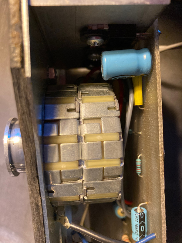
What’s the best way to test the motor? As pic shows, there are two wires (grey, black) coming from one part, and two wires (red, grey) coming from other.
Total motor newbie, sorry.
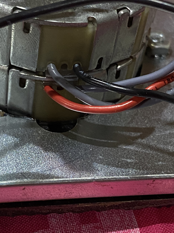
Just check the resistance of each pair of wires, r-gy and b-gy. You should see around the same value for each. You can also check the resistance of the silver capacitors, should be open-circuit. TBH the chances of passive components failing is very low, ditto the motor.
Well, I googled and tried to test coil resistance.
About 26-27ohms resistance from red to it’s counterpart grey and same from black to its counterpart grey.
Looks okay, right?
About 26-27ohms resistance from red to it’s counterpart grey and same from black to its counterpart grey.
Looks okay, right?
- Home
- Source & Line
- Analogue Source
- Sota TT Motor Board Mishap