Are there any Sugden fans who might be able to shed some light on this unit?
Beautiful wiring, soldering and the feeling throughout of an utterly hand assembled unit but would appreciate some more insight and background.
I think WAL stands for Wellington Acoustic Laboratories, more than that I don’t know.
Would be grateful if anyone can comment on its likely sound quality.
To work as a phono preamp would it require an outboard RIAA?
What would be its best role in a system? Could it work as just a sitting box?
I haven’t yet fired connected it up, are there any readings I could check with a DMM?
Attachments

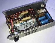
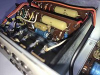
The components go back a lo-o-o-ng way. I recall those polyester caps from near 60 years ago and those carbon composition resistors?....well, they were phased out by most manufacturers in the early 1970s. The electrolytic caps probably should all be replaced with similar style axial lead types where possible, before attempting to power the unit up. It's possible to spread the leads of commonly available radial leaded caps too, as long as there is room to realign the cap and add insulation sleeving as necessary.
The unit was likely designed for use in commercial installations, as the industrial looking fascia, box and mounting brackets seem to suggest. It may even be a reasonable, if rather basic preamp including a phono preamp too, but at the time, the "phono" section probably only suited a high output, piezo crystal type phono cartridge. These are virtually extinct now, replaced by much lower output, magnetic cartridges which require proper RIAA type equalization, as built into more elaborate, domestic hifi preamps. Unless you already have such a player with a crystal type cartridge , just forget this feature - it definitely won't impress with high fidelity.
To be honest, I think its more a collector's piece than practical preamp but if you have need of a bench preamp for tinkering with amplifiers, this is simple and robust enough. With a recap of the electrolytics, it may be fine for even another 50 years.
I think "disc" refers to phonograph records and not CDs, so there is probably RIAA eq on that input.
Yes, definitely not compatible with CDs but for crystal or piezo type phono cartridges, the eq. was usually quite rudimentary and seldom conformed to any standard (there were several EQ standards in use around the world, back them) because many commonly available cartridges didn't either. A nominal 12dB level variation across the audio band may have been compensated for but not often with any accuracy.
Popular cartridges were "turnover" type too. You flipped the cantilever round 180 deg. and could then have a sapphire 78 RPM stylus for Bakelite as well but what EQ should have applied there?
Popular cartridges were "turnover" type too. You flipped the cantilever round 180 deg. and could then have a sapphire 78 RPM stylus for Bakelite as well but what EQ should have applied there?
Thanks guys.
Ian, that's wonderfully informative, thank you.
I've also been advised that it might be best to disconnect the psu section prior to powering up the unit in order to be confident about psu's output. Sound sensible? Could one just desolder the three leads at the point where they attach to the amp boards?
Initial response on the unit from the manufacturer..
- The unit hasn't been seen before.
- The circuit boards are not from another Sugden product.
- It was built for a special purpose, possibly part of a test rig.
- The circuit boards are estimated at 1967-8.
- The unit hasn't been seen before.
- The circuit boards are not from another Sugden product.
- It was built for a special purpose, possibly part of a test rig.
- The circuit boards are estimated at 1967-8.
That's understandable. The time was long ago with different people in a different location and Sugden was then probably still feeling its way in the industry, taking on a wider range of business than just audio power amplifiers and interconnects.
If you want to test the power supply alone, the advice to disconnect and test its output voltage (whatever that is supposed to be) makes sense, provided you can locate that point where its output goes to the preamp.
First, you don't have a schematic circuit diagram to follow but you'll need it eventually and you'll have to sketch your own from the parts and wiring in front of you. Its not that hard when you know what to look for which means knowing at least the basics of simple, single DC output power supplies and how to identify the likely components.
Google is your friend for the basics and there are plenty of docs about simple, transformer based power supplies out there. However, you'll find everything necessary to know about audio, projects, theory and about such power supplies in the power supply design section here: DIY Audio Articles
Last edited:
Update..
The manufacturers are sure that it was designed by Jim Sugden.
Apparently a variac can sometimes cause instability issues.
Plugged it in to the mains and no smoke or pops to report.
Can anyone suggest some DMM readings that I could take from inputs and outputs that might offer some reassurance prior to linking it up to my audio system?
Hi, just adding some info and readings to this thread, apologies for the radio silence.
Looking at the readings, can anyone advise as to whether they look fine or are there any issues about which I should be concerned? Naturally, I don't want to risk any samge to my amplifiers or speakers (Celestion Ditton 66's)
My intention is to try it out as a phono amp which will then be connected to a pre amp (NAD 3020A pre section) which will in turn be connected to a power amp.
I realise that an RIAA filter may have to be added to make this work.
Does any one particular channel look to have better readings than the rest?
Any to avoid?
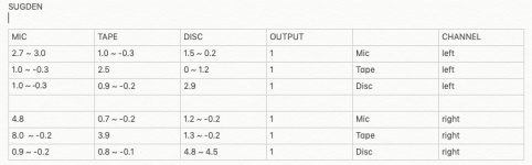
MIC TAPE DISC OUTPUT CHANNEL
2.7 ~ 3.0 1.0 ~ -0.3 1.5 ~ 0.2 1 Mic left
1.0 ~ -0.3 2.5 0 ~ 1.2 1 Tape left
1.0 ~ -0.3 0.9 ~ -0.2 2.9 1 Disc left
4.8 0.7 ~ -0.2 1.2 ~ -0.2 1 Mic right
8.0~ -0.2 3.9 1.3 ~ -0.2 1 Tape right
0.9 ~ -0.2 0.8 ~ -0.1 4.8 ~ 4.5 1 Disc right
The above chart displays the DMM DC readings in mV for each of the I/O sockets.
The I/O socket from which the reading was taken are written in capitals at the top of the columns.
The position setting on the rotary lever switch are written in lower case at the right hand end of the rows.
When the rotary switch was turned a higher reading (90mV, 70mV, even a 170mV) would briefly flicker in between the selector registering in the new setting. Is this a concern?
Looking at the readings, can anyone advise as to whether they look fine or are there any issues about which I should be concerned? Naturally, I don't want to risk any samge to my amplifiers or speakers (Celestion Ditton 66's)
My intention is to try it out as a phono amp which will then be connected to a pre amp (NAD 3020A pre section) which will in turn be connected to a power amp.
I realise that an RIAA filter may have to be added to make this work.
Does any one particular channel look to have better readings than the rest?
Any to avoid?
MIC TAPE DISC OUTPUT CHANNEL
2.7 ~ 3.0 1.0 ~ -0.3 1.5 ~ 0.2 1 Mic left
1.0 ~ -0.3 2.5 0 ~ 1.2 1 Tape left
1.0 ~ -0.3 0.9 ~ -0.2 2.9 1 Disc left
4.8 0.7 ~ -0.2 1.2 ~ -0.2 1 Mic right
8.0~ -0.2 3.9 1.3 ~ -0.2 1 Tape right
0.9 ~ -0.2 0.8 ~ -0.1 4.8 ~ 4.5 1 Disc right
The above chart displays the DMM DC readings in mV for each of the I/O sockets.
The I/O socket from which the reading was taken are written in capitals at the top of the columns.
The position setting on the rotary lever switch are written in lower case at the right hand end of the rows.
When the rotary switch was turned a higher reading (90mV, 70mV, even a 170mV) would briefly flicker in between the selector registering in the new setting. Is this a concern?
First, DC at the input or output of a preamp shouldn't be there. There will always be some tiny current leakage but ideally, zero, as you would measure with a film type capacitor that would normally be in that location. The problem for you and anyone helping, is that there is no schematic diagram and we can only guess what that is, what the cap. types and the expected voltages are.
At this point, I would sketch out a schematic for yourself. It's not difficult to do if you can recognize what the components and values are. They aren't hard to decipher, nor is the hand-wired circuit hard to trace on a relatively simple device like this. You may need to draft it a few times to arrange the circuit it in a logical sequence but that will be to your lasting benefit, and make things easier to follow for all.
Electrolytic Capacitor leakage allows DC to appear where it shouldn't be and it definitely shouldn't be easily measureable. The figures are showing a little too much DC, if they are measured with respect to signal input ground. When you change the input settings though, the DC levels will jump about until the charges are dis-charged, according to the connections, circuit load and the tiny load presented by your meter.
That said, I don't think DC measurements at the input are what you need to know to determine whether the preamp is suitable for audio needs. The measurements needed are sensitivity to AC (audio) signals , for which you'd likely need an oscilloscope and a low level signal source to be accurate. For comparison, a moving iron magnetic cartridge preamp has to work with as low as 2mV output but a ceramic piezo cartridge can produce 150mV or so and some early crystal types are much higher output, in the volts range, so you need quite different amounts of amplification and impedance matches before making assumptions about this unit's capabilities. I doubt it's anywhere near sensitive enough for magnetic cartridges but I could be wrong - who knows what Sugden actually had in mind for it.
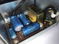
Current leakage of old caps is a sign they are on the way out, if not already dead. Even high quality electrolytic caps won't last 50 years or more so the unit is well past a proper service, including replacing those blue sleeved electrolytics. Do that before you think about putting any vintage electronics to use. If you were wanting to keep everything looking original, you'll need to put new caps inside the old cans because old caps don't fix themseves - they must be replaced but modern equivalents are a lot smaller so it's not all that difficult, assuming you can buy axial rather than radial leaded types.
Most amplifier inputs will also have series capacitors to protect the amplifier from DC anyway but if neither caps are in good shape, you don't have that protection and you could soon be frying your preamp and the amp. with DC. Don't leave it that way - replace electrolytic caps. Also from memory, the powder coated shell of those Philips/Mullard types I think, (buff colour) polyester caps, tends to crack open. If you notice any caps like that, replace with a modern MKT type equivalents or if size permits, ideally could be Polypropylene or MKP type.
At this point, I would sketch out a schematic for yourself. It's not difficult to do if you can recognize what the components and values are. They aren't hard to decipher, nor is the hand-wired circuit hard to trace on a relatively simple device like this. You may need to draft it a few times to arrange the circuit it in a logical sequence but that will be to your lasting benefit, and make things easier to follow for all.
Electrolytic Capacitor leakage allows DC to appear where it shouldn't be and it definitely shouldn't be easily measureable. The figures are showing a little too much DC, if they are measured with respect to signal input ground. When you change the input settings though, the DC levels will jump about until the charges are dis-charged, according to the connections, circuit load and the tiny load presented by your meter.
That said, I don't think DC measurements at the input are what you need to know to determine whether the preamp is suitable for audio needs. The measurements needed are sensitivity to AC (audio) signals , for which you'd likely need an oscilloscope and a low level signal source to be accurate. For comparison, a moving iron magnetic cartridge preamp has to work with as low as 2mV output but a ceramic piezo cartridge can produce 150mV or so and some early crystal types are much higher output, in the volts range, so you need quite different amounts of amplification and impedance matches before making assumptions about this unit's capabilities. I doubt it's anywhere near sensitive enough for magnetic cartridges but I could be wrong - who knows what Sugden actually had in mind for it.
Current leakage of old caps is a sign they are on the way out, if not already dead. Even high quality electrolytic caps won't last 50 years or more so the unit is well past a proper service, including replacing those blue sleeved electrolytics. Do that before you think about putting any vintage electronics to use. If you were wanting to keep everything looking original, you'll need to put new caps inside the old cans because old caps don't fix themseves - they must be replaced but modern equivalents are a lot smaller so it's not all that difficult, assuming you can buy axial rather than radial leaded types.
Most amplifier inputs will also have series capacitors to protect the amplifier from DC anyway but if neither caps are in good shape, you don't have that protection and you could soon be frying your preamp and the amp. with DC. Don't leave it that way - replace electrolytic caps. Also from memory, the powder coated shell of those Philips/Mullard types I think, (buff colour) polyester caps, tends to crack open. If you notice any caps like that, replace with a modern MKT type equivalents or if size permits, ideally could be Polypropylene or MKP type.
Last edited:
cb1;6662272 I realise that an RIAA filter may have to be added to make this work. [/QUOTE said:Most likely, the 'disc' channel will have RIAA. Disc used to be the name for record replay, not Compact Disk.
Jan
Thanks Jan, appreciated. Although some have suggested that the unit might predate having RIAA. e.g. using ceramic cartridges etc. I'll probably try the Tape input as well as the Disc and see if I can hear a difference.
Thanks Ian for another comprehensive and interesting post.
So the major contributor to the DC readings is most likely the electrolytic caps. When replacing them on the amp boards should I try to use Nichicon UKL / Panasonic FC's?
And over by the transformer use, say, Nichicon UPW / Panasonic FM or equivalents?
"When the rotary switch was turned a higher reading (90mV, 70mV, even a 170mV) would briefly flicker in between the selector registering in the new setting."
Would these bursts, whilst turning the rotary selector probably be very audible? And should new caps bring these readings down towards zero, or could anything else cause these readings?
Thanks again.
The bursts are the clicks we hear when switching sources on a lot of older amplifiers with minor leaky cap issues. There is always some tiny discrepancy in voltage levels between source and preamp. Though small discharges may be annoying, they're usually harmless. Larger bursts could even blow your speakers and the amplifier output stage too. It's a matter of degree whether any damage is done though.
The caps here are not required to smooth the DC from a power supply rectifier as in a power amp, so instead of those hard-working types that are commonly discussed in this amplifier forum, we could need low leakage electrolytic types which are more appropriate for blocking low level DC. Having said that, there are exceptions and a lack of supply for those specialised types forces DIYs to change their plans and sometimes, newer products perform better across the board and may be fine in this role too. A Google search for "low leakage caps" turns up some interesting facts and posts elsewhere too.
The appropriate capacitor types to use and a lot of other things won't be clear until there is schematic so I can only suggest you make a start on it by inspecting the parts already fitted and identifying their values, including the grey coloured Philips/Mullard transistors which are possibly in the BC5XX series, such as 547,8,9. Much of this will become clear to us when there is a schematic. Until then, its guesswork and as it stands, the preamp is unlikely to give you better than mediocre performance for your purpose.
I neglected the small power supply which does, of course, have smoothing caps but consider that you don't need massive capacitors for the small, <50mA current requirement and any reasonable brand and grade capacitors such as Rubycon, Nippon Chemicon, Elna etc - even RS Components' house brand will be fine. The modern equivalents will be much smaller and as you require rare, axial leaded types, you'll likely have to compromise and solder insulated wires to extend the existing ones. I wouldn't try to fit expensive boutique type parts until the preamp proves to do what you actually want with acceptable performance. It's 1960s gear and audio standards weren't always hifi.
Thanks again Ian.
So these caps in the power supply, I should go with the brands mentioned and should I be looking especially for 'low leakage' or is there some other trait that's more beneficial?
So these caps in the power supply, I should go with the brands mentioned and should I be looking especially for 'low leakage' or is there some other trait that's more beneficial?
The main power supply caps should not be low leakage types. As said, modern electrolytic capacitors have all-round improved performance on the types that were available when this little beast was conceived. It means standard, good quality caps will be quite fine in all but signal coupling duties. In that special role, they are generally small value capacitors, chosen to allow full frequency bandwidth AC to pass but block all DC from entering the following stages and causing havoc with noise and critical DC voltage levels there. Note that the polarity of these caps is critical to their proper operation - at the very least keep a note or pencil the polarity somewhere near the cap before removing any that are mounted to tag boards and point-to-point wired.
As a simple explanation of grades and types, electrolytics are classified according to form factor, (as in squat, tall, compact etc), lead types (axial, radial alignments, screw connections or PCB snap-in type, lifetime ratings of so many thousand hours at so much duty cycle. That's right, cheap caps don't last long in heavy duty applications. For light signal level duties of most electrolytic caps though, its a waste of money specifying super heavy duty grade power supply caps with amazing specs and prices where other qualities would serve better.
Again, it would be guessing to suggest what specific caps these should be without that schematic. You may be trying to skip drawing anything just by blanket capacitor replacement yet have no clue what you're doing without knowing or being able to communicate what the design is. This doesn't help or augur well for using the device, modifying it etc. for your actual needs as they arise. It also makes it near impossible to help constructively without just adding to the guesswork.
Last edited:
- Home
- Amplifiers
- Solid State
- Sugden preamp wal ac farnell