Just starting with this concept from an introduction in the TV tubes forum. Basically I do not know what I am doing but pieced together knowledge from George's thread and Smoking-amps' posts.
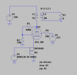
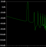
I created a LTSpice model of an SE output stage (shown below). I kind of guessed at the Schade resistor values and the screen voltage as I was not sure of the theory to select those. I used a 6L6 model for the output tube. I am worried I did something wrong because the sim seems to good to be true. I know sims sometimes can be used to be sure something is good but it sure tell if something is bad. I got 10W out with 2nd and 3rd harmonics 40db down.
I created a LTSpice model of an SE output stage (shown below). I kind of guessed at the Schade resistor values and the screen voltage as I was not sure of the theory to select those. I used a 6L6 model for the output tube. I am worried I did something wrong because the sim seems to good to be true. I know sims sometimes can be used to be sure something is good but it sure tell if something is bad. I got 10W out with 2nd and 3rd harmonics 40db down.
Attachments
Last edited:
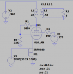
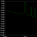
Ok, here is one that wont melt the glass. ~9W at ~0.4% THD
Increased R1 to lower the DC current to about 50ma. I am still not sure what I am doing visavie R1, R2 and screen voltage.
Increased R1 to lower the DC current to about 50ma. I am still not sure what I am doing visavie R1, R2 and screen voltage.
Attachments
Last edited:
I think your numbers are probably overly optimistic but the performance of the circuit is very good. Somewhere, George posted a pdf of distortion measurements. You'll probably want to refer to those to get an idea of how the circuit performs in real life.
Different MOSFET's will have quite a spread of currents for the same VGS. LTspice will not show this. You may well need some way of adjusting the voltage with a trimmer to set bias current. The valve models on diyaudio are usually very accurate. Could you fix the grid voltage and take the FB to the MOSFET gate with say 47k input series resistor. Just an idea.
For almost every sweep tube I have tested the optimum resistor ratio is 10:1. Use 300K from plate to grid, and 30K from grid to ground. This ratio sets the amount of "triodeness" that you get from the tube. It also sets the control grid voltage.
Set the idle current by adjusting the bias voltage on the mosfet (the DC offset on the source). The real amps I have made have a pot on the gate to adjust the bias. That's the three resistors seen in my sim.
The optimum screen voltage for most sweep tubes is 150 to 175 volts. Start with 150 volts measured from screen to cathode. This means that the screen to ground voltage will be dependent on the bias (source offset) voltage. My UNSET board runs a screen supply of about 175 volts. The cathode voltage is around 60 to 65 volts. Idle screen to cathode voltage is about 110 volts increasing to 170 at full current.
You should notice that both the screen and control grids are driven by the signal voltage as the cathode moves toward ground when the stage is driven into more conduction. The control grid is also driven by the negative feedback from the plate, so it sees signal and feedback voltages. All voltages are in phase here, so the complete stage does not invert the signal. Care is needing in decoupling a multi stage amp.
I will try to get more details about the theory and operation together and put it in the UNSET thread on the Tubelab forum. I had surgery Wednesday and am not well recovered yet. Be back to diyAudio when I can.
TY. Hope you feel better soon. As mentioned in the other TV forum I am interested in trying this on a 807(1625).
Best wishes for a speedy and full recovery George.
The incidental role of the screen grid is interesting here, since it is providing some screen grid drive when just anchored to a DC voltage.
Might be interesting to put an N Mosfet follower on grid 2 and then provide some mix (a pot for testing) of feedback from the plate and the fixed V to control Vg2. Would be curious if the distortion could be minimized or something like tuning the amount of 2nd harmonic for triode mode.
notice that both the screen and control grids are driven by the signal voltage as the cathode moves toward ground when the stage is driven into more conduction. The control grid is also driven by the negative feedback from the plate, so it sees signal and feedback voltages.
The incidental role of the screen grid is interesting here, since it is providing some screen grid drive when just anchored to a DC voltage.
Might be interesting to put an N Mosfet follower on grid 2 and then provide some mix (a pot for testing) of feedback from the plate and the fixed V to control Vg2. Would be curious if the distortion could be minimized or something like tuning the amount of 2nd harmonic for triode mode.
Maybe I'm looking at the schematic wrong way around but shouldn't the FET be an N-Channel such as an IRF840?😕
Otherwise the DC current has nowhere to go.
Otherwise the DC current has nowhere to go.
I assume that you are looking at the schematic that's in post #1 and #3. If so the fet is a P channel since it is a follower with it's drain connected to ground.
I tend to avoid the use of silicon devices in tube amps in the usual common source configuration due to it's nonlinearity. I use them in follower, CCS, and split load PI duty only.
I tend to avoid the use of silicon devices in tube amps in the usual common source configuration due to it's nonlinearity. I use them in follower, CCS, and split load PI duty only.
Maybe I'm looking at the schematic wrong way around but shouldn't the FET be an N-Channel such as an IRF840?😕
Otherwise the DC current has nowhere to go.
My earlier post expressing confusion, did this kind of circuit originate in one of John Broskie's notes on the 'Inverted Cascode"? After a 2nd look I think it works as is.🙂
- Home
- Amplifiers
- Tubes / Valves
- First sim of UNSET circuit