Hi everyone!
A couple of years ago I bought two of these DIYINHK Power Supply DIY sets and built them up. Only now did I get to put them to work, but they only work with open load so far 😱. The items are EOL, but I'd like to use them anyway:
The driven load needs +/-15V with max. 800mA per Rail.
The DIY supply supposedly drives up to 1.5A per rail at +/-15V.
The Supply used so far is a Meanwell PD-2515 which matches the current needs.
The measured actual current drawn by the load from the +15V rail is 590mA and 550mA from the -15V rail.
Observation is that the Output voltage of the DIY supply drops from +/-15V to +/-12V on one unit and even down to 10.5V on the other unit when the load is applied.
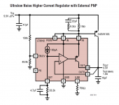
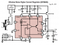
I have reverse engineered the board schematic (hopefully correctly...) and as comparison a basic application schematic from the LT3042 datasheet. Please see attachments.
Any hint what may be wrong or how I could proceed to make the boards work as intended would be much appreciated.
Thanks and Regards,
Winfried
A couple of years ago I bought two of these DIYINHK Power Supply DIY sets and built them up. Only now did I get to put them to work, but they only work with open load so far 😱. The items are EOL, but I'd like to use them anyway:
The driven load needs +/-15V with max. 800mA per Rail.
The DIY supply supposedly drives up to 1.5A per rail at +/-15V.
The Supply used so far is a Meanwell PD-2515 which matches the current needs.
The measured actual current drawn by the load from the +15V rail is 590mA and 550mA from the -15V rail.
Observation is that the Output voltage of the DIY supply drops from +/-15V to +/-12V on one unit and even down to 10.5V on the other unit when the load is applied.
I have reverse engineered the board schematic (hopefully correctly...) and as comparison a basic application schematic from the LT3042 datasheet. Please see attachments.
Any hint what may be wrong or how I could proceed to make the boards work as intended would be much appreciated.
Thanks and Regards,
Winfried
Attachments
Someone posted a message which is now gone... The suggestion was to measure the Input DC after rectification with and without load. I will do that and post the result.
Thanks anyway,
Winfried
Thanks anyway,
Winfried
Hi,
what do you use as voltage source in your setup ?
What you bought is only a regulator for positive and negative voltages. Do you use a transformer with bridge rectifier and some caps as input voltage ?
You need a higher input voltage to receive a stable output. The higher the current, the more voltage gets burned in the regulator.
So under no load you can input +/-15V and will perhaps receive +/-15V at the output. But the higher the current, the more voltage you will need. You loose the dropout voltage. At 1A for example you will need +/-17V to have a stable +/-15V at the regulator outputs (only example numbers, look in the specs for exact numers).
If you use the Meanwell as input, then this is the problem, you need a higher input voltage, so the regulator delivers stable +/-15V.
Second point is, that 800mA out of this regulator PCB will make it run very hot, you will need good cooling. If this PCB really uses the LT3042, then i also dont know, why they say its 1A max. Datasheets say that this regulators max output current is 200mA.
But first you need to tell us, which kind of input voltage you use. Transformer ? What voltages ?
The OP used a Meanwell PD-2515 power supply which supplies +-15V. He needs to input higher voltages like you suggest.
@ Linuxgeek
Dear friend, thanks for your thought, but while your points are very valid, I'm sorry to say they suggest that you did not look at the attachments provided in the lead in post. They show the boards and the schematic, so should answer some of your questions.
@ all
Anyway, the story took a different turn when measuring the Rectifier Output Voltages, a bit embarrassing 🙄 : The Transformer is actually a 30VA R-core which I had handy. Obviously I had misred the printed 2x15V as 2x18V - wishful thinking...
So, I'll rejumper the DIYINHK board for +/-12V Output and test if this works better under load condition, which I very much expect. If or once this works I'll decide to buy a 2x18V Transformer or what else to do/try...
Thanks everyone,
Greetings,
Winfried
@ Linuxgeek
Dear friend, thanks for your thought, but while your points are very valid, I'm sorry to say they suggest that you did not look at the attachments provided in the lead in post. They show the boards and the schematic, so should answer some of your questions.
Not really, i saw the pictures, but they say nothing about your AC->DC part and the voltage there.
If you use an R-Core transformer 2x15V is enough. After rectification you should receive about 18V if using a full bridge rectifier and some uF of caps for stabilization.
I still think that you run into problems with the regulator ICs. If this regulator circuit uses only single ICs for the rails, you will run into major problems at over 500mA. I also used the LT3042 ICs and mine went nuts when current was over 500mA. They were also pretty hot and like i said, the datasheets say, they are meant for 200mA max current.
@ Linuxgeek
OK, let's address the issues:
The +Output of the DF01S bridge rectifier (please see board schematic) measures a suspicious +15V= without load (which drops to +12.5V= with 550mA Load). The negative Regulator (not shown on schematic) shows similar bahavior. This seems to point towards the Transformer having an issue...?
The board schematic shows a D45VH10G Power transistor connected to the +Out Pin of the DF01S as well as LT4032 Pin1 and Pin10. Looking at the pictures on the DIYINHK website shows the cooled power transistors as well. So powerwise this should work. It's somehow hard to believe that both Powertransistors should be gone (and why)...?
Regards,
Winfried
- Home
- Amplifiers
- Power Supplies
- DIYINHK Supply: Please help to make it work...