Guys,
I am trying to diagnose a loudspeaker that I bought as a kit. I believe there may be an issue with the engineering of the bass unit. The woofer has been fitted in a more or less standard cabinet (for that supplier) and does not sound right to me.
I have spent vast amounts of time reading up. I have found many references to the work of Martin King, George Ausperger, Bob Brines etc. Unfortunately the alignment tables, worksheets etc. mentioned can be found nowhere, and now I am stuck.
I hope that someone could point me in the right direction. If the documents are free for sharing, I hope that someone is willing to do so.
I am a practical guy looking for a solution. I am willing to share the details of the design (drawing of box) and woofer. Maybe someone is willing to help?
I have measured the line length, SI and SO and the terminus size.
Last edited:
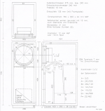
I have enclosed the TSP for the woofer and also the cabinet drawing.
I tried to determine the following parameters:
I tried to determine the following parameters:
- Line surface at start (at the baffle) 724 cm2
- Line surface directly behind the woofer 535 cm2
- Line surface at terminus 254 cm2
- Terminus 170 cm2
Attachments
Had another look and, yeah, I now see the option for mass loaded TL.
I hope I am not the only one who thinks that this software is only usable if you are already an expert? I am not even going to try it. There are too many inputs that I don't understand or require guesswork.
Surely, this can't be all that's available?
I hope I am not the only one who thinks that this software is only usable if you are already an expert? I am not even going to try it. There are too many inputs that I don't understand or require guesswork.
Surely, this can't be all that's available?
That does not look like a well designed TL, not taking advantage of now fairly standard practice.
Looks like someone took the Bailey/Radford/IMF/TDL designs and said this looks about the right size. I do not expect it to be anywhere near optimal.
I do not doubt a much more effective line could be designed. What eaxactly is the woofer.
The MJK worksheets are the gold standard, hornResp is now the available goto. A modeler is really really useful but with so many degrees of freedom, knowing what you are doing is essential. Get out and play.
If those currently active, look out for Scottmoose, GM, or pkitt posts. Scott & i just did a tribute box to Bob.
dave
Looks like someone took the Bailey/Radford/IMF/TDL designs and said this looks about the right size. I do not expect it to be anywhere near optimal.
I do not doubt a much more effective line could be designed. What eaxactly is the woofer.
The MJK worksheets are the gold standard, hornResp is now the available goto. A modeler is really really useful but with so many degrees of freedom, knowing what you are doing is essential. Get out and play.
Martin King, George Ausperger, Bob Brines etc.
If those currently active, look out for Scottmoose, GM, or pkitt posts. Scott & i just did a tribute box to Bob.
dave
I looked at hornresp. I am not sure it can be used for my type of cabinet.
Yes, it can, search in the Hornresp help file for "transmission line"
That was my exact thought. Any time a driver is located at the very beginning of the line, unless it's for only subwoofer use, I know it's going to be very difficult to get an acceptable, much less an optimal performance from it.
Paul
Paul
That does not look like a well designed TL, not taking advantage of now fairly standard practice.
Looks like someone took the Bailey/Radford/IMF/TDL designs and said this looks about the right size. I do not expect it to be anywhere near optimal.
I do not doubt a much more effective line could be designed. What eaxactly is the woofer.
The MJK worksheets are the gold standard, hornResp is now the available goto. A modeler is really really useful but with so many degrees of freedom, knowing what you are doing is essential. Get out and play.
If those currently active, look out for Scottmoose, GM, or pkitt posts. Scott & i just did a tribute box to Bob.
dave
Paul,
The only successful end-loaded line Scot t& i have done is the microTower tribute. The box came first and it was already end-loaded.
https://www.diyaudio.com/forums/full-range/148901-microtower-bipolar-ml-tl-chr-70-el70.htm
dave
The only successful end-loaded line Scot t& i have done is the microTower tribute. The box came first and it was already end-loaded.
https://www.diyaudio.com/forums/full-range/148901-microtower-bipolar-ml-tl-chr-70-el70.htm
dave
The woofer is an Audio Technology 10A7725KAP. It was supposed to be custom made for this speaker, to match the cabinet. In this design it is crossed over at about 400 Hz (LR4 active), so it's not just subwoofer.
The cabinet is built very well and finished too (did you see the 2" inch baffle for instance?). I very much want to keep using the cabinet. It looks good too 🙂
From my limited understanding, the tapered line has a resonant frequency corresponding to 1/4 of the wavelenth. As the line is about 1,75 meters, the res. frequency ~50 Hz (seems too high).
Fortunately, mass loading apparently lowers this frequency. So, maybe just changing the terminus, which can be done easily and out of view, might bring improvements.
If I cannot calculate it, is there a way to measure this?
The cabinet is built very well and finished too (did you see the 2" inch baffle for instance?). I very much want to keep using the cabinet. It looks good too
I have speculated that simply putting the woofer on the back of that style TL to create some Zd. That makes the back 2” thick.
Is the baffle braced against the res of the box? I ask as a properly braced 18mm baffle will outperform a 2” without. If you want overkill, double 18mm baffle plus brace.
A tapering (large to small) resonates at a lower frequency than ¼ Fs, so if tapered it should be shorter.
dave
The woofer is an Audio Technology 10A7725KAP. It was supposed to be custom made for this speaker, to match the cabinet. In this design it is crossed over at about 400 Hz (LR4 active), so it's not just subwoofer.
The cabinet is built very well and finished too (did you see the 2" inch baffle for instance?). I very much want to keep using the cabinet. It looks good too 🙂
From my limited understanding, the tapered line has a resonant frequency corresponding to 1/4 of the wavelenth. As the line is about 1,75 meters, the res. frequency ~50 Hz (seems too high).
Fortunately, mass loading apparently lowers this frequency. So, maybe just changing the terminus, which can be done easily and out of view, might bring improvements.
If I cannot calculate it, is there a way to measure this?
Can you post the T/S parameters of this driver here?
This woofer has an ideal TS parameters for vented box with about 57 litres internal volume! F3=35 Hz with tuning at Fb=25 Hz.I have enclosed the TSP for the woofer and also the cabinet drawing.
Do not complicate with TL enclosure, especially with that outdated, plain wrong design.
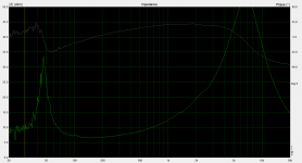
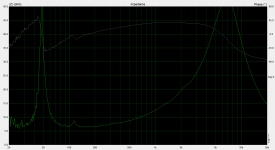
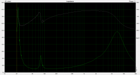
I did some measurements.
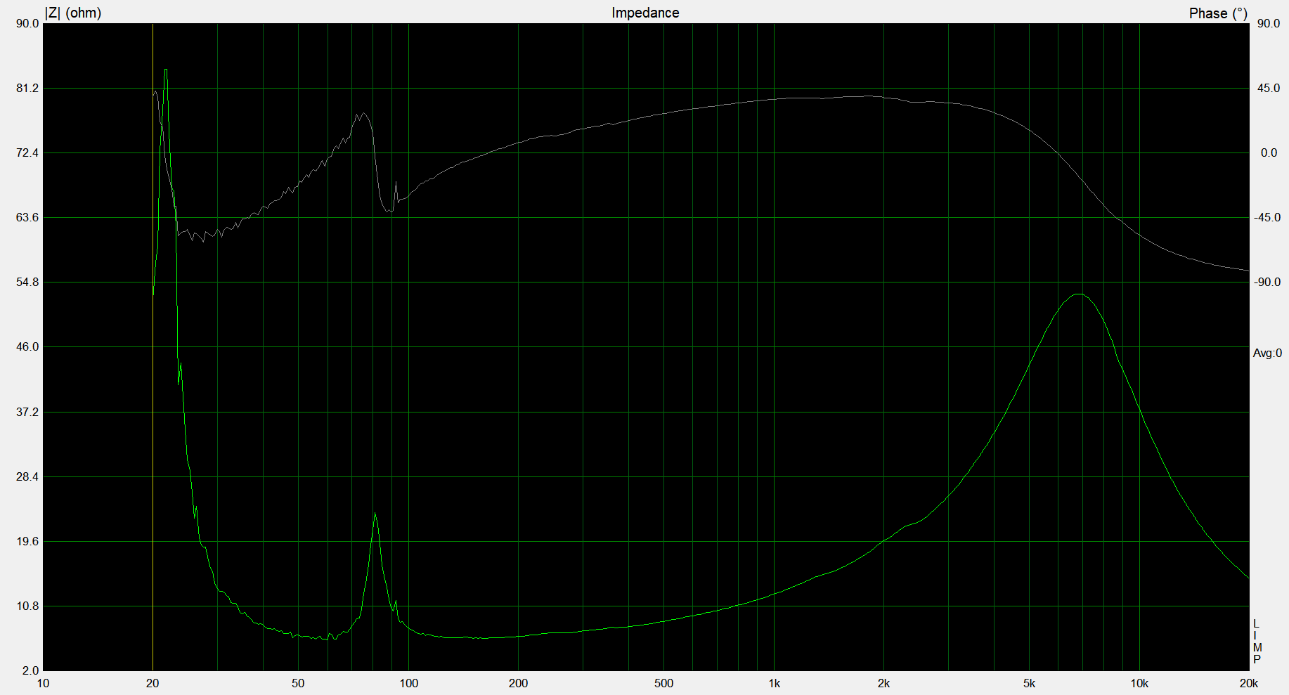
When the box is open, the impedance peaks at 22 Hz which is close the the Fs of the woofer

With the box closed, the impedance peaks at 49 Hz, which is very closed to the quarter wave frequency of the line.
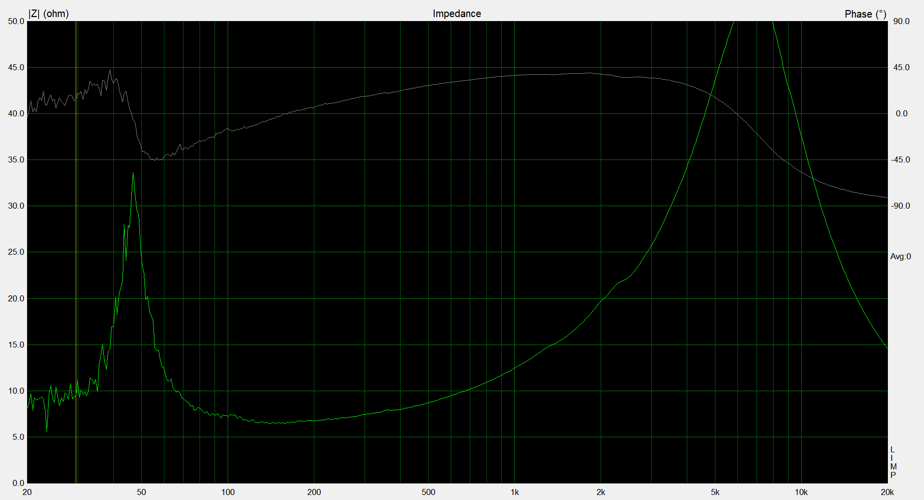
When the box is stuffed, the resonance is damped. Fs unchanged.
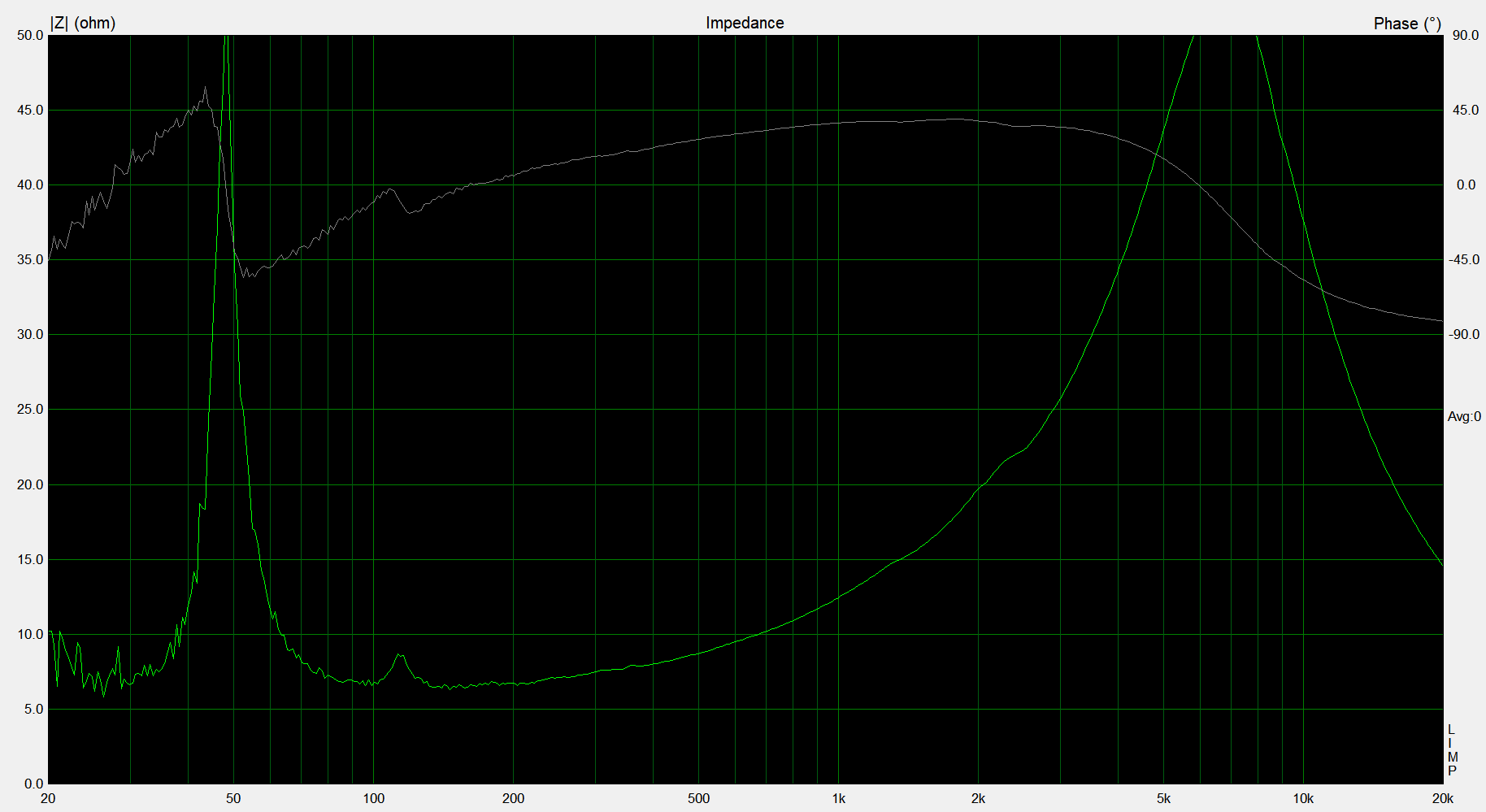
I blocked a part of the terminus, expecting the peak in the impedance would shift lower. I didn't. ****!
Hope anyone can comment. Is there a way to align the box with the woofer better?
Edit: I thought putting the url for the images in the text would make them show there.
When the box is open, the impedance peaks at 22 Hz which is close the the Fs of the woofer
With the box closed, the impedance peaks at 49 Hz, which is very closed to the quarter wave frequency of the line.
When the box is stuffed, the resonance is damped. Fs unchanged.
I blocked a part of the terminus, expecting the peak in the impedance would shift lower. I didn't. ****!
Hope anyone can comment. Is there a way to align the box with the woofer better?
Edit: I thought putting the url for the images in the text would make them show there.
Attachments

Last edited:
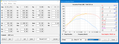
Since I got no responses, and I was being haunted by the problem, I decided to face Hornresp's steep learning curve.
The results are pretty awasome though.
Here is the modeled response (half space)
https://www.diyaudio.com/forums/attachment.php?attachmentid=927513&stc=1&d=1614604920
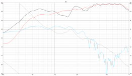
And here the measured response (nearfield + baffle step)
https://www.diyaudio.com/forums/attachment.php?attachmentid=927507&stc=1&d=1614604920
I am quite surprised about the accuracy (I didn't play the number to arrive at the wanted response). I think I now understand the fundamental problem of this design.
I tried, but couldn't model a reasonably small adjustment to the cabinet to improve the response. The changes I tried only gave slight differences.
I am now considering converting the box to sealed. It shouldn't be much work to gut and close the cabinet, add bracing and some stuffing. The result would be a sealed alignment with a Qtc of about 0,5 and F6 around 38 Hz. I may add a linkwitz transform to arrive at F6=24 Hz (!) applying only 6 dB of gain (and free choice of Qtc).
Is this a real option for this woofer? How accurate is VentuixCAD in this respect (modeling sealed box)?
The results are pretty awasome though.
Here is the modeled response (half space)
https://www.diyaudio.com/forums/attachment.php?attachmentid=927513&stc=1&d=1614604920
And here the measured response (nearfield + baffle step)
https://www.diyaudio.com/forums/attachment.php?attachmentid=927507&stc=1&d=1614604920
I am quite surprised about the accuracy (I didn't play the number to arrive at the wanted response). I think I now understand the fundamental problem of this design.
I tried, but couldn't model a reasonably small adjustment to the cabinet to improve the response. The changes I tried only gave slight differences.
I am now considering converting the box to sealed. It shouldn't be much work to gut and close the cabinet, add bracing and some stuffing. The result would be a sealed alignment with a Qtc of about 0,5 and F6 around 38 Hz. I may add a linkwitz transform to arrive at F6=24 Hz (!) applying only 6 dB of gain (and free choice of Qtc).
Is this a real option for this woofer? How accurate is VentuixCAD in this respect (modeling sealed box)?
Attachments
Last edited:
Unfortunately the [MJK] alignment tables, worksheets etc. mentioned can be found nowhere
Change the .txt to .xls and hopefully will open/work correctly.........
Attachments
Since I got no responses..........I tried, but couldn't model a reasonably small adjustment to the cabinet to improve the response. The changes I tried only gave slight differences.
Just now seeing this and little time nowadays to devote much time on any forums, but as already discussed, the major problem is the driver not being offset to fill in the huge dip in response and it strong harmonics that required excessive damping.
BTW, IIRC I found the MJK 'Classic' Alignment info I posted on the web archive, so anytime wanting dead link stuff, many old textbooks among other things............
Last edited:
I am now considering converting the box to sealed. It shouldn't be much work to gut and close the cabinet, add bracing and some stuffing. The result would be a sealed alignment with a Qtc of about 0,5 and F6 around 38 Hz. I may add a linkwitz transform to arrive at F6=24 Hz (!) applying only 6 dB of gain (and free choice of Qtc).
Is this a real option for this woofer? How accurate is VentuixCAD in this respect (modeling sealed box)?
With Hornresp you could also simulate Closed Box. Why don't you try it?
- Home
- Loudspeakers
- Multi-Way
- Modeling of a ML tapered line