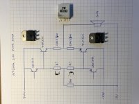
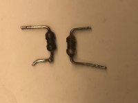
I have a plate amp from a subwoofer that has a blown output. The two power transistors (TIP35/36C) have gone short. One of the 0R15 resistors has gone open in the resistor package and then there are two tiny resistors that have released thier magic smoke. Any ideal what the value of these is likely to be?
One measures 42.6 ohms and the other 1K47 but I assume they would have been the same value
I hope I have drawn the circuit right. TIA
One measures 42.6 ohms and the other 1K47 but I assume they would have been the same value
I hope I have drawn the circuit right. TIA
Attachments
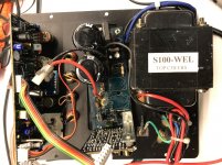
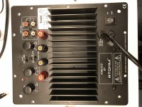
Ylli, the amp is a plate amp from a Waterfall Sub. The amp is made by Atohm and has the designation S100 on the PCB but I can't find any material on it.
I'm looking for simalar circuits on the web
I'm looking for simalar circuits on the web
Can you see any color bands on either of the resistors? Overloaded resistors don't fail low, but fail high or open. I would suspect the 43 ohm resistor is the original value and the one that measures 1.5k has been overloaded and gone high. But why one would fail and the other not is strange.
But then 43 ohms is a 5% value, and I would expect that they would use 10% values such as 39 ohm or 47 ohm in that location as the value is not hyper-critical.
Do check the driver transistors to be sure they are not also blown, then I think I would use 47 ohm resistors for the driver emitters. Too low and the drivers will run hot, to high and the output may have some high frequency instability (increased turn off time).
But the above is only a guess.....
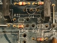
Although this is a French company (I think) the build reminds me of early Chinese/Japanese products with components mounted at any angle and holes far too large for the leads. When I was going through the board I did find a few weak/dry joints.
The other resistors around the area have Gold bands (5%) and I think are about 1/8th watt (~4mm long).
I'll swap out the drive transistors anyway while I'm at it, just waiting for the components to arrive.
Fortunately the speaker seems fine. I'm driving it with another amp and no strange smells or sounds.
Attachments
And what about the rest of the transistors? What drives the drivers?
(Many circuits might have a VAS stage that could fail too. Some VAS stages are inherently protected by current limiting. Need to see the circuit diagram to know).
(Many circuits might have a VAS stage that could fail too. Some VAS stages are inherently protected by current limiting. Need to see the circuit diagram to know).
Unfortunatly I have no schematics. There are two additional boards. One has the filters and input buffers and the other seems to be the amp driver board. With the final two stages on the board with the PSU attached to the heatsink.
The 2SC3117/2SA1249 transistors drive the final stage before the TIPs and I thought these were good but on closer inspection the 2SA1249 has a 3.9ohm short between collector and base. I was planning on changing these anyway.
So yes I'm checking the driver board now
The 2SC3117/2SA1249 transistors drive the final stage before the TIPs and I thought these were good but on closer inspection the 2SA1249 has a 3.9ohm short between collector and base. I was planning on changing these anyway.
So yes I'm checking the driver board now
Attachments
Made in China, never meant to be repaired so no service info available. All too typical nowadays unfortunately.
Craig
Craig
There does seem to be level of complexity to design given its task. The output stage looks fairly conventional. Just need to work out the values of the crispy resistors.
It does have clipping detection and thermal protection but it did not save it.
Part of me is thinking it would be quicker to replace it with a class d amp.
It does have clipping detection and thermal protection but it did not save it.
Part of me is thinking it would be quicker to replace it with a class d amp.
Ylli already suggested 39 or 47 ohms. I agree, it would not be critical as 100 ohms was also common. I'd suggest 47 as a sort of close fit but a fried resistor isn't going to give you much of a clue as to what it was.
But I am concerned it is not your only problem.
But I am concerned it is not your only problem.
- Home
- Amplifiers
- Solid State
- Help with component values please?