Good morning Guys,
Does anyone have any ideas/experience of using an AGC type circuit in the preamp stage to allow for different line input levels and thus preventing overdriving of the later stages?
Does anyone have any ideas/experience of using an AGC type circuit in the preamp stage to allow for different line input levels and thus preventing overdriving of the later stages?
I haven't but logically in order for AGC to work there must be a "sensing " feedback circuit with error correction , then you have the problem of sensing TIME and possible noise distortion introduced ( or mixed ) into the original signal.
AGC or AVC is widely used in RF communications equipment including normal radios and was and is a means of stopping signal overload but radio isn't very low distortion high end quality comparable to very best audio designs with up to minus 100db distortion.
AGC or AVC is widely used in RF communications equipment including normal radios and was and is a means of stopping signal overload but radio isn't very low distortion high end quality comparable to very best audio designs with up to minus 100db distortion.
Thanks
Thanks Guys,
As a radio/RF engineer this is something I do indeed see every day, I was just wondering if this was a technique that was in "normal" use in the tube/Audio frequency world having seen so many different "standards" for line input levels quoted in texts. Maybe its just that a proper design would not need this and I'm over thinking it ?
Modern digital audio signal sources exhibit a max. 2 VRMS signal level. If older sources require different handling, you can simply set up custom "padding" at the I/P jacks. Commercial "line level" equipment must be able to drive the IHF "standard" 10 Kohm load. Tube/valve equipment typically has an I/P impedance >= 100 Kohms. So, an approx. 10 Kohm total resistive voltage divider at an I/P jack fed by a CDP is not a problem.
The downside to resistive voltage divider "padding" is damage to S/N performance. If low noise 1% tolerance metal film resistors are used, said damage is minimal.
The downside to resistive voltage divider "padding" is damage to S/N performance. If low noise 1% tolerance metal film resistors are used, said damage is minimal.
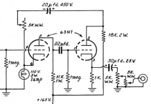
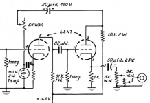
Well, here is an idea.Good morning Guys,
Does anyone have any ideas/experience of using an AGC type circuit in the preamp stage to allow for different line input levels and thus preventing overdriving of the later stages?
Mona
Attachments
Mona,
Is the idea behind what you provided a varying resistance in the incandescent lamp controlled by the O/P signal level? That varying resistance would change the common cathode gain block's bias voltage.
Is the idea behind what you provided a varying resistance in the incandescent lamp controlled by the O/P signal level? That varying resistance would change the common cathode gain block's bias voltage.
I think you're more likely to come across soft clipping techniques like Wavebourn uses in his designs.
Yes, resulting in more or less negative feedback.Mona,
Is the idea behind what you provided a varying resistance in the incandescent lamp controlled by the O/P signal level?
Shure, but it's only to show a possible way to atack the problem.That varying resistance would change the common cathode gain block's bias voltage.
The bias and feedback part could be separated.
Mona
Attachments
I wouldn't use a normal AGC to interfere with the signal ... what happens in low/high level passages , pauses and so on ? Even with some delay time . The RF signal in a radio/tv doesn't change in this way 😀 and the audio is of course modulated in it .
Maybe something that is working just at startup to select the right gain . Simplified some comparators and relays
Maybe something that is working just at startup to select the right gain . Simplified some comparators and relays
Last edited:
Good point about the quiet passages Depanatoru ! I think we're back to soft compression of the signal.......or just have the preamp stage gain set up correctly for the particular expected input level as previously mentioned, which is i think the right way to go. Maybe I'm overthinking this ?
It's not tubes, but it's interesting. Maybe there's a schematic that could be worked for tubes...
FP-ALC2 ‐ Automatic Level Control - Stereo - RCA Jacks
FP-ALC2 ‐ Automatic Level Control - Stereo - RCA Jacks
Does anyone have any ideas/experience of using an AGC type circuit in the preamp stage to allow for different line input levels and thus preventing overdriving of the later stages?
There is no audio AGC circuit and there can't be. This is not a matter of circuit design, it's simple logic. The circuit CAN'T know if you selected a high output source or a low output source playing a very loud song.
There are, however, many kinds of compressors, as Koda pointed to. Look for dbx 118 and 128.
If you don't want to bother turning the volume up and down when you switch sources, you can simply put a volume control on each input. Commonly done on commercial gear.
Attachments
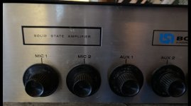
In one of my first preamps ( well it 's a KF101 board) i mounted adjustment pots at each input adjusting them to equal volume from tape radio and phone. This like a loop connector is what's missing on nearly all preamps. The same amp used mercury-wetted relays mounted close to the inputs as signal selectors avoiding long cables and complex switches.Good morning Guys,
Does anyone have any ideas/experience of using an AGC type circuit in the preamp stage to allow for different line input levels and thus preventing overdriving of the later stages?
Electronics:
If you have widely different signal levels coming out of different signal sources, then putting potentiometers at each RCA input jack makes sense.
But, if multiple potentiometers is too much trouble for you, instead have a single volume control right after the input selector switch. Be near the volume control to turn it up or down as necessary.
If you are concerned that you will incorrectly adjust the volume control, so that there is more distortion, if you can not hear or discern that level of distortion, what are you worried about?
Adding a couple of other triodes to the signal path, will it add some more distortion, and will that worry you?
With extremely different signal levels, how much dynamic range does the compressor have to have before it distorts badly?
And, when you play a vinyl record, are all records recorded at the same level?
Are all CDs recorded at the same level?
Are all FM stations using the same level of modulation (actually many are, because they compress it to death, so that you can hear all the [compressed] music in a noisy car).
Soft clipping is a great thing, if you like that effect.
At least it prevents grungey sound.
Music:
Compression is a 'distortion' of both the songwriter's and the conductors's intents.
The triple Forte marking at the end of Haydn's surprise symphony, when compressed will destroy the musical content of the piece.
This is a distortion of the Music.
It is not Harmonic distortion, and it is not Intermodulation distortion.
Quite a different animal.
Just my opinions, as an amplifier designer, as a music listener (live and recorded),
and as a musical performer.
Your Mileage, and Your Happiness May Vary.
Last edited:
...different line input levels and thus preventing overdriving of the later stages?
If nobody is listening, who cares?
If someone is listening, someone can turn it down.
In my power amps I sense screen grid currents of output tubes to control input optical attenuators. Such a way the amp avoids hard clipping decreasing volume at peaks. Also, in series with current sensing LEDs I am adding "overload" indicator bright red LEDs, to see that the sound is being compressed/limited.
- Home
- Amplifiers
- Tubes / Valves
- Any ideas ?