Hi folks
Back in 2018 I built up a pair of Camp Amp v1.0 PCBs and a BOZ, but due to illness they have sat in a box ever since.
I'm finally getting round to doing something with them, I'd like to build an integrated amp and was wondering if the BOZ & these Amp Camp modules would work well together.
How large do the heatsinks for the Amp Camp modules need to be? I have quite a few heatsinks of various sizes I could use.
What sort of power supply arrangement would be most suitable for powering the Amp Camp modules? Again, I have a variety of power supply components I can select from.
This is going to be my first attempt at building my own amp, so forgive any potentially silly questions.
Last edited:
Looking through the Amp Camp article I found this info on the power requirements:
"Each channel of the amplifier has its own switching power supply and draws about 1 amp of current DC. The supply should be capable of delivering more than 2 amps of current short term. "
I have a pair of regulator circuits I built using the LT1086 which is rated for 1.5A, will this be sufficient, or does the "more than 2 amps of current short term" mean I need to use regulators that can handle over 2A?
After reading the post about the mod to increase the bias:
Amp Camp Amp - ACA
I am pretty sure I will need more juice than an LT1086 can provide as the mod increases power draw:
"Just did the tweak, it pulls instead of 0.98 A now 1.40 A, and on the AC side it pulls 34 Watt instead of 21 Watt."
I have a pair of regulator boards I made up using LT1083s, those are rated at 3A, so I think I'll use those.
hi Ian,
the size of the heatsinks is 200mm x 80mm x 40mm with 10mm baseplate
numbers taken from the store's kit chassis.
cheers
A.
the size of the heatsinks is 200mm x 80mm x 40mm with 10mm baseplate
numbers taken from the store's kit chassis.
cheers
A.
Ian:
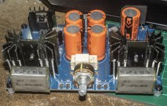
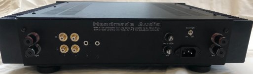
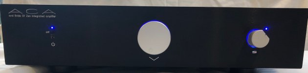
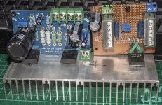
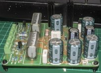
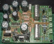
I built an integrated amplifier for my elder daughter and her fiancé (now her husband) about 2 years ago that consisted of a Bride of Zen preamplifier and a bridged Amp Camp Amp (i.e., two ACAs per channel). The project was housed in a HiFi2000 2U Dissipante chassis, which is available at the diyAudio store. During the burn-in period, I never noticed the heatsinks getting more than slightly warm. My daughter tells me she listens to the amp often and is very pleased with it. You could undoubtedly do a lot worse.
Regards,
Scott
Attachments
Cheers guys, this is all very useful. That's a lovely amp Scott, thanks for sharing, seeing how other people have done similar things is very useful to a noob like me. I see several similarities to what I was envisaging - namely two toroidals, one to power the ACAs and one for the preamp, also I was going to mount a pair of rectifiers upside down bolted to the chassis as you have, and your smoothing cap banks are similar to what I was planning to use too.
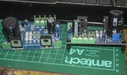
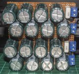
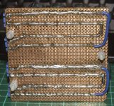
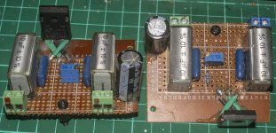
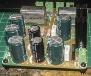
I've included some pics of the LT1038 regulator boards I have, from memory, I just copied the circuit in the datasheet. I was figuring I could attach them to the main heatsinks next to the amp modules and use two banks of smoothing caps before the regulators to make a fairly good power supply. I have the cap bank pictured already made, it is two banks of 8 x 2200uF 25v Samsung caps with a 0.1uF poly cap at the end of each string.
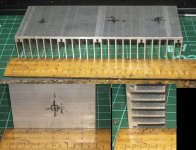
The heatsinking is going to be a problem as the largest ones I have that will fit in the chassis I was going to use are only 150x60x25, just the right size vertically to fit in the chassis and just wide enough to fit the amp module and a regulator.
In the amp camp document Nelson says the heatsink should not get hotter than 25 degrees above ambient, so do folks think these smaller heatsinks I have are sufficient (quite possibly the heatsinks sold in the kit are oversized just because bigger is better?) or do I really need to use something with more mass of aluminium?
If I need to go bigger, I will have to find a larger chassis, which will cause a significant delay in the project.
Maybe I should build the thing using these smaller heatsinks and see how hot it runs, then if it's getting too hot, revise it with bigger heatsinks and a bigger chassis that will accommodate them?
I've included some pics of the LT1038 regulator boards I have, from memory, I just copied the circuit in the datasheet. I was figuring I could attach them to the main heatsinks next to the amp modules and use two banks of smoothing caps before the regulators to make a fairly good power supply. I have the cap bank pictured already made, it is two banks of 8 x 2200uF 25v Samsung caps with a 0.1uF poly cap at the end of each string.
The heatsinking is going to be a problem as the largest ones I have that will fit in the chassis I was going to use are only 150x60x25, just the right size vertically to fit in the chassis and just wide enough to fit the amp module and a regulator.
In the amp camp document Nelson says the heatsink should not get hotter than 25 degrees above ambient, so do folks think these smaller heatsinks I have are sufficient (quite possibly the heatsinks sold in the kit are oversized just because bigger is better?) or do I really need to use something with more mass of aluminium?
If I need to go bigger, I will have to find a larger chassis, which will cause a significant delay in the project.
Maybe I should build the thing using these smaller heatsinks and see how hot it runs, then if it's getting too hot, revise it with bigger heatsinks and a bigger chassis that will accommodate them?
Attachments
Last edited:
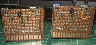
I note that Scott used the JFET version of the BOZ and I just happen to also have a completed one of that version too. I don't actually know what the difference is without studying the documents.
Is there any appreciable difference between them that would influence which version I happened to use in conjunction the the ACA?
Is there any appreciable difference between them that would influence which version I happened to use in conjunction the the ACA?
Attachments

May I ask where you sourced those knobs?
Dennis:
Thank you! Both knobs are aluminum. The larger one is 48mm in diameter and is readily available on eBay and AliExpress. The smaller one is 25 or 28mm in diameter, and I believe it was purchased on a business trip to India (somewhere in Mumbai, I think). It may also be available online, but it's certainly harder to find.
Ian:
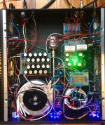
It's impossible to tell from the middle photo on my post above, but there are two cap boards for the power supply; I used twenty short 4700 uF 35V caps per ACA channel. That proved adequate for my bridged build; if you're committed to just a single pair of ACA boards, you could likely do well with less.
Good luck!
Regards,
Scott
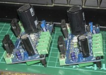
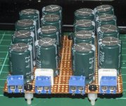
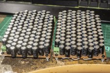
Thanks for the info Scott. I have several cap banks I built but never used, to go to the other extreme of what I have I could use these two, each composed of 107 x 470uF 50v caps giving a total of 50,290uF per bank.
I actually have another pair of unpopulated ACA boards and probably have all the parts to build them apart from the output Mosfets. I do have loads of power mosfets but I don't think I have four more IRFP240s, but I can always buy some.
I'm wondering if a single pair of ACAs will drive the speakers I intended to use to adequate levels, or if I should do as you did and bridge two pairs.
Attachments
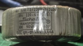
I have been sorting through the pile of trafos I have and so far, the only one I have found that might be suitable is this Schaffer with a 26V 3.46A output. However, I am not sure if it has the correct secondary windings for powering a pair of ACAs. It had three secondary wires, which I take to be two 26v lines and a common ground, which would work for a +/- 26V dual rail supply, but can this trafo be used to power a pair of single rail 26v supplies?
If not, I know I have a few other trafos in a box in my storage shed, so I need to drag that box out and have a look.
If not, I know I have a few other trafos in a box in my storage shed, so I need to drag that box out and have a look.
Attachments
Cheers guys, this is all very useful. That's a lovely amp Scott, thanks for sharing, seeing how other people have done similar things is very useful to a noob like me. I see several similarities to what I was envisaging - namely two toroidals, one to power the ACAs and one for the preamp, also I was going to mount a pair of rectifiers upside down bolted to the chassis as you have, and your smoothing cap banks are similar to what I was planning to use too.
I've included some pics of the LT1038 regulator boards I have, from memory, I just copied the circuit in the datasheet. I was figuring I could attach them to the main heatsinks next to the amp modules and use two banks of smoothing caps before the regulators to make a fairly good power supply. I have the cap bank pictured already made, it is two banks of 8 x 2200uF 25v Samsung caps with a 0.1uF poly cap at the end of each string.
The heatsinking is going to be a problem as the largest ones I have that will fit in the chassis I was going to use are only 150x60x25, just the right size vertically to fit in the chassis and just wide enough to fit the amp module and a regulator.
In the amp camp document Nelson says the heatsink should not get hotter than 25 degrees above ambient, so do folks think these smaller heatsinks I have are sufficient (quite possibly the heatsinks sold in the kit are oversized just because bigger is better?) or do I really need to use something with more mass of aluminium?
If I need to go bigger, I will have to find a larger chassis, which will cause a significant delay in the project.
Maybe I should build the thing using these smaller heatsinks and see how hot it runs, then if it's getting too hot, revise it with bigger heatsinks and a bigger chassis that will accommodate them?
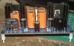
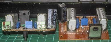
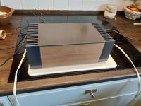
I have built one of the Chinese copies, and am in the process or rebuilding it.
The thing at the bottom is the MK1 with a 19V SMPS from a laptop.
The heat sinks ran at above 60 degrees Celsius.
I have since then rebuilt it and made the modifications for 24V and I am currently running it from a 200VA 2x18V transformer followed by one rectifier bridge per winding followed again by a single 10.000uF capacitor.
Each channel has its own bridge and capacitor.
I get a noticeable buzz from this setup that disappears if I use a SMPS.
Since I have already built the case I will have a hard time fitting a larger capacitor bank I ordered a 24V 144W SMPS instead.
I will place that inside the case and later, when I get bored and the kids give me a few minutes to myself I'll make a proper (THE best word in the English dictionary) CRC PSU and test.
My new case has the heat sinks in the upper part of the photo and they are running just below 60 degrees Celsius.
So my thought, totally devoid of knowledge, is that yours should run around the same temperature as my first try.
Attachments

That's very useful and interesting, thanks for sharing.
I hit a problem with mine - the metal box I was going to use as a chassis has disappeared from my storage shed, so I have had to buy another and am waiting for it to arrive.
60C doesn't sound too bad, although I'm still thinking of using larger heatsinks than the ones I have - the new chassis should accommodate a lager set of heatsinks.
- Home
- Amplifiers
- Pass Labs
- Integrated using BOZ + Camp Amp v1.0