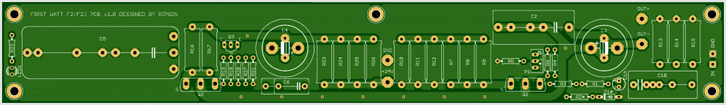
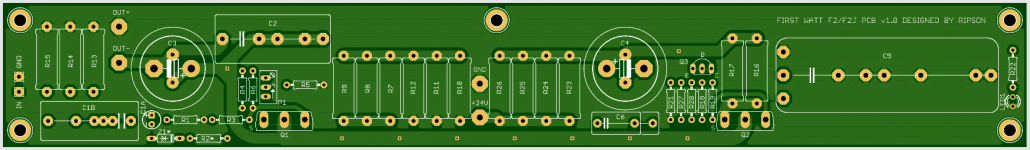
Up for sale is a set of 3 PCBs for Nelson Pass FIRST WATT F2 and F2J (only 4 sets available):
left channel + right channel + power supply.
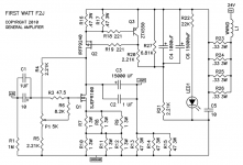
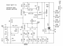
I’m not going to prepare the BOM file, but below are the details that should help to choose elements by yourself, I have also attached the schematics.
CAPACITORS:
C1A - grid: 2.5mm, diameter: 5mm
C1B - grids: 5mm, 7.5mm, 10mm, 15mm, 22.5mm - max width: 10mm
C2 - grids: 10mm, 15mm, 22.5mm, 27.5mm - max width: 13mm
C3, C4 - grids: snap-in 10mm and 7.5mm THT, max diameter: 23mm
C5 - grids: 15mm, 22.5mm, 27.5mm, 37.5mm, 52.5mm, and the last one around 56.5mm, max width: the width of the board actually, so 55x40mm should fit here.
C6 - grids: 10mm and 15mm - max width 6.4mm
RESISTOR:
low wattage resistors:
grid: 10mm
max diameter: 2.8mm
max wire diameter: 0.8mm
power resistors:
grid: 17mm
max diameter: 6.3mm
max wire diameter: 1mm
Please note that Z1 and R2 are only used in F2 (when IRFP240 is used instead of SJEP120R100 as Q1)
The PCBs are made of standard fiberglass epoxy laminates FR4 with the standard 1.6oz/ft2 thick copper, hot air solder leveling with lead - BTW I am using the soldering tin 60/40 for my projects and I don't use RoHS Pb-free crap tin with silver. The high current paths are 115mil on both sides. The path between MOSFET drains is double 150mil, so the temperature at idle current of about 2A rises only 0.11°C above the ambient. The track clearance is 0.8mm (31.5mil), which's enough for 24V according to the standards.
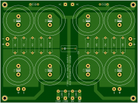
The power supply board:
size: 160.2 x 120.2 mm
mounting holes: 150 x 110 mm
Please pay attention to R9 and R10 resistors on the PSU board marked with *, these aren’t 0R47, using these will definitely cause a short circuit, these are 2.2k.
The amplifier boards:
size: 279.5 x 39.5mm
mounting holes: 270 x 30mm
- the center mounting hole is 140mm from the hole located at the edge.
The mounting holes are 3.2mm for M3 standoffs located at the multiplication of 10mm, so it's possible to mount them at the grid with the same grid of holes – like in modushop.
PCB are going to be ready for sale from 20 Februrary 2021.
The price is $29 per set + shipping.
left channel + right channel + power supply.
I’m not going to prepare the BOM file, but below are the details that should help to choose elements by yourself, I have also attached the schematics.
CAPACITORS:
C1A - grid: 2.5mm, diameter: 5mm
C1B - grids: 5mm, 7.5mm, 10mm, 15mm, 22.5mm - max width: 10mm
C2 - grids: 10mm, 15mm, 22.5mm, 27.5mm - max width: 13mm
C3, C4 - grids: snap-in 10mm and 7.5mm THT, max diameter: 23mm
C5 - grids: 15mm, 22.5mm, 27.5mm, 37.5mm, 52.5mm, and the last one around 56.5mm, max width: the width of the board actually, so 55x40mm should fit here.
C6 - grids: 10mm and 15mm - max width 6.4mm
RESISTOR:
low wattage resistors:
grid: 10mm
max diameter: 2.8mm
max wire diameter: 0.8mm
power resistors:
grid: 17mm
max diameter: 6.3mm
max wire diameter: 1mm
Please note that Z1 and R2 are only used in F2 (when IRFP240 is used instead of SJEP120R100 as Q1)
The PCBs are made of standard fiberglass epoxy laminates FR4 with the standard 1.6oz/ft2 thick copper, hot air solder leveling with lead - BTW I am using the soldering tin 60/40 for my projects and I don't use RoHS Pb-free crap tin with silver. The high current paths are 115mil on both sides. The path between MOSFET drains is double 150mil, so the temperature at idle current of about 2A rises only 0.11°C above the ambient. The track clearance is 0.8mm (31.5mil), which's enough for 24V according to the standards.
The power supply board:
size: 160.2 x 120.2 mm
mounting holes: 150 x 110 mm
Please pay attention to R9 and R10 resistors on the PSU board marked with *, these aren’t 0R47, using these will definitely cause a short circuit, these are 2.2k.
The amplifier boards:
size: 279.5 x 39.5mm
mounting holes: 270 x 30mm
- the center mounting hole is 140mm from the hole located at the edge.
The mounting holes are 3.2mm for M3 standoffs located at the multiplication of 10mm, so it's possible to mount them at the grid with the same grid of holes – like in modushop.
PCB are going to be ready for sale from 20 Februrary 2021.
The price is $29 per set + shipping.
Attachments

Last edited:
all boards sold out, that was quick, thank you guys!
Nice layout and price is great, no wonder they are already sold out.
BR
Eric

- Status
- Not open for further replies.