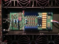
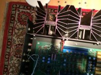
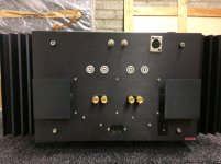
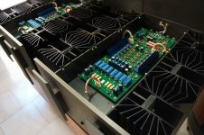
Just bought a pair of Krell KRS-100 Class A fixed bias amps from around the year 1992. They look somewhat similar to the bigger PassLabs designs like the XA-160 which are Class A fixed bias amps also.
After extensive search on the Internet and trying to contact its designer Dan d' Agostino I got nothing apart from a measurement report from a German technician that mentioned they deliver 236 Watss @ 8 Ohms and 426 @ 4 Ohms with 1% THD and "very harmoniously falling harmonic distortion" whatever that means.
I wish to adjust bias and offset (I know which trimmers I have to use) but I have no data, diagrams or service-manual. Now they take around 600 Watts from the AC outlet and they're not quite similar in surfacetemperature.
A user from this forum told me regarding a KRS-200 that this design consumes 7 Amps of bias to reach his 4 Ohm rating all in Class A.
Sadly Dan d'Agostino was not willing to help me and said I should contact his former employer Krell Industries which I maybe will but I do not expect anything from them either.
Nelson Pass helped me a bit out as generous he always his with sharing his knowledge even about his former designs like Threshold, but I feel a bit inhibited to bother him to much about designs he did not craft.
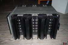
The first three pictures are from the actual unit the last two from the Internet.
Maybe someone can point me in the good direction.
Thanks in advance.
https://www.diyaudio.com/forums/attachment.php?attachmentid=918623&stc=1&d=1612427111
https://www.diyaudio.com/forums/attachment.php?attachmentid=918624&stc=1&d=1612427111
https://www.diyaudio.com/forums/attachment.php?attachmentid=918625&stc=1&d=1612427111
https://www.diyaudio.com/forums/attachment.php?attachmentid=918626&stc=1&d=1612427111
https://www.diyaudio.com/forums/attachment.php?attachmentid=918627&stc=1&d=1612427111
After extensive search on the Internet and trying to contact its designer Dan d' Agostino I got nothing apart from a measurement report from a German technician that mentioned they deliver 236 Watss @ 8 Ohms and 426 @ 4 Ohms with 1% THD and "very harmoniously falling harmonic distortion" whatever that means.
I wish to adjust bias and offset (I know which trimmers I have to use) but I have no data, diagrams or service-manual. Now they take around 600 Watts from the AC outlet and they're not quite similar in surfacetemperature.
A user from this forum told me regarding a KRS-200 that this design consumes 7 Amps of bias to reach his 4 Ohm rating all in Class A.
Sadly Dan d'Agostino was not willing to help me and said I should contact his former employer Krell Industries which I maybe will but I do not expect anything from them either.
Nelson Pass helped me a bit out as generous he always his with sharing his knowledge even about his former designs like Threshold, but I feel a bit inhibited to bother him to much about designs he did not craft.
The first three pictures are from the actual unit the last two from the Internet.
Maybe someone can point me in the good direction.
Thanks in advance.
https://www.diyaudio.com/forums/attachment.php?attachmentid=918623&stc=1&d=1612427111
https://www.diyaudio.com/forums/attachment.php?attachmentid=918624&stc=1&d=1612427111
https://www.diyaudio.com/forums/attachment.php?attachmentid=918625&stc=1&d=1612427111
https://www.diyaudio.com/forums/attachment.php?attachmentid=918626&stc=1&d=1612427111
https://www.diyaudio.com/forums/attachment.php?attachmentid=918627&stc=1&d=1612427111
Attachments
Biasing is easy to figure out if you know the class A power the unit was set to deliver. And of course the impedance. The max power won't tell you anything as at some point the amps switch into AB. Krell Industries is likely your best bet for info.
Yes I know. Just gave those figures as a reference.
I'm in the progress of adjusting those amps right now.
Got some info from the importer over here and it is basically the same bias adjust procedure as on the Levinson ML-2's:
The positive lead of your MM connected at the positive ouputterminal and the negative lead at one of the emitterresistors as a testpoint.
Check all six coolingtowers and adjust for 500 mV at the highest one of the six.
The of course a DCO rating of less than 10 mV.
The last four of these coolingtowers from Levinson ML-2 had (first two counting from the frontplate were the regulators) should be adjusted for 550 mV.
Would love the have some "official" data about these amps.
https://www.diyaudio.com/forums/attachment.php?attachmentid=918633&stc=1&d=1612431647
Attachments

Both amps now adjusted for 650 Watts AC intake when idling.
Got a mail from a nice German guy who wanted to share some data with me which is great of course. His units where served by a technician that does this for some thirty years or so (Herr Diplom. Ingenieur Rolf Kassel) with highend stuff and he had them adjusted for 700 Watts. With regard on the safe rating for each coolingtower of 130 Watts and having six of the totalling to 880 Watts, these seems to be conservative figures.
Got a mail from a nice German guy who wanted to share some data with me which is great of course. His units where served by a technician that does this for some thirty years or so (Herr Diplom. Ingenieur Rolf Kassel) with highend stuff and he had them adjusted for 700 Watts. With regard on the safe rating for each coolingtower of 130 Watts and having six of the totalling to 880 Watts, these seems to be conservative figures.
Somewhere, can't remember where, I saw an article explaining that Krell adjusted the bias something like this:
After powering on with a dummy load connected and leaving the temperature to stabilise, a square wave of frequency xxxx Hz is connected to the input at a level xxx mV. The square wave is monitored with a scope at the output, and the biasing is adjusted till a distortion can be seen of the square wave. The bias is then adjusted down till the signal "cleans" up.
Not certain if this is true or not.
Good luck, Kevin
<quote>Somewhere, can't remember where, I saw an article explaining that Krell adjusted the bias something like this:
After powering on with a dummy load connected and leaving the temperature to stabilise, a square wave of frequency xxxx Hz is connected to the input at a level xxx mV. The square wave is monitored with a scope at the output, and the biasing is adjusted till a distortion can be seen of the square wave. The bias is then adjusted down till the signal "cleans" up.
Not certain if this is true or not.
Good luck, Kevin</quote>
You are right.
A former Krell technician just confirmed this...
A former Krell technician just confirmed this...
Really? This sounds utterly incredible.
He literally said:
"The only way to correctly set bias is with a Distortion analyzer, load banks and scope."
and
"There is next to no written info for this unit…the engineer never released a schematic to the service department.
There were only some hand drawn circuits from myself and other techs from back in the 80’s.
There are also at least 3 different audio board circuits all with different bias settings. And 4 different transformer configurations.
So there were basically many changes during its build life that were never documented."
And what's really frightening:
"When correct with a proper pre-amp, these unit will produce a wonderful sound stage with a fat low mid bump.. (never connect tube pre-amp to this unit or any Krell amp, it will defiantly explode or cause issues with the front end.)"
- Home
- Amplifiers
- Solid State
- Krell KRS-100