Hi,
I have a problem with my CD67. The CD motor started behaving intermittently, then stopped working altogther (apart from slight slow speed movements when mains power is applied or removed). The motor itelf is OK with the correct resistance according to the motor specs. After close onspection of the 'CD Eng Decoder' board, I noticed an SMD component was missing on the reverse side of the board. It looks like one side of the device had been manually retouched sometime during manufacture, but not very well, allowing the component to eventually detach itself.
I couldn't find the missing part, but it is in the motor driver circuit, between a dual op-amp compensator and the dual transistor driver stage. It is a 0805(?) size component immediately to the left of a silk screen legend '3151', not far from the mid cable-tie for the digital i/o cable. The 3151 code suggests (based on the CD66 schematic) that it might have been a resistor, but I cannot determine the value as the CD67 seems to have different component values to the CD66. The item is in series with a blue coloured SMD component marked '1003' (100k resistor?) which is then connected to pin 6 of the dual op-amp 7131 (JRC 4560D).
I was wondering if anyone with access to a schematic or a working unit could let me know the value of the missing SMD component.
Thanks in advance.
What is the component ref number? a description of parts around it is no good, unless we have sight of the board.
Jon,
Thanks for the reply. I am not sure about the part number as not every SMD component has a silk-screen identifier. As I mentioned there is a 3151 reference immediately to the right of the component. I did think of submitting a photo of the relevant area of the board, but didn't want to chance a rejection first posting. Would a photo of the general vicinity be of help?
Thanks for the reply. I am not sure about the part number as not every SMD component has a silk-screen identifier. As I mentioned there is a 3151 reference immediately to the right of the component. I did think of submitting a photo of the relevant area of the board, but didn't want to chance a rejection first posting. Would a photo of the general vicinity be of help?
I can't help with ID but would just mention that it is not uncommon for manufacturers to modify boards after production.
Are you 100% sure 'something has fallen off" as that seems a little unlikely?
It would have to fail in both ends of the soldering and also any adhesive would have to fail. I suspect it is probably original.
Are you 100% sure 'something has fallen off" as that seems a little unlikely?
It would have to fail in both ends of the soldering and also any adhesive would have to fail. I suspect it is probably original.
I am sure something has fallen off. Prior to my fixing a case of 'cog rot', the CD player was fully functional (apart from tray issue). After fixing 'cog rot', the CD playback was initially intermittent and finally ceased altogether after extensive probing around, removing and reinserting IDC cables, etc. I have checked motor conitinuity from the servo board output actually on the 'CD Eng Decoder' board and that is fine. The motor does 'twitch' when the unit mains is applied and removed.
I have attached a close in view of the area. There is clear evidence of reworking on the SMD solder joint on the '3' side of the device (uppermost in image). It has a distinct rounded, silvery appearance, unlike the typical gritty-grey look of most connect solder joints elsewhere on the board. The other solder connection shows a clear outline of the wave-soldered connection. The main power input terminals and some of the digital i/o connector joints on the board also have been reworked with a similar shiny appearance. To me, it looks like the rework did not wet the SMD contact, creating a proximity contact, just waiting to fail under mechanical movement.
I have attached a close in view of the area. There is clear evidence of reworking on the SMD solder joint on the '3' side of the device (uppermost in image). It has a distinct rounded, silvery appearance, unlike the typical gritty-grey look of most connect solder joints elsewhere on the board. The other solder connection shows a clear outline of the wave-soldered connection. The main power input terminals and some of the digital i/o connector joints on the board also have been reworked with a similar shiny appearance. To me, it looks like the rework did not wet the SMD contact, creating a proximity contact, just waiting to fail under mechanical movement.
Attachments
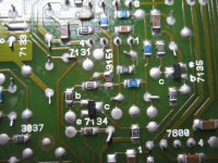
Your last picture shows that most probably you're right. Something has fallen off the PCB. I suspect that the 3151 number doesn't relate to the missing component, though. Look at all the other numbers. There are just two of them, 7134 and 7135, that _might_ be related to transistors, while the others appear to be randomly distributed (but surely aren't, of course). You need to find a service manual.
Best regards!
Best regards!
Your last picture shows that most probably you're right. Something has fallen off the PCB. I suspect that the 3151 number doesn't relate to the missing component, though. Look at all the other numbers. There are just two of them, 7134 and 7135, that _might_ be related to transistors, while the others appear to be randomly distributed (but surely aren't, of course). You need to find a service manual.
Best regards!
Kay,
I have access to the CD66 schematic (the CD67 service manual is worse than useless!) and the first digit of the 4 digit code seems to indicate component type: '1' = generic (incl connectors and crystals), '2' = capacitor, '3' = resistor, '5' = inductor, '7' = semiconductor including IC.
The CD67 circuit seems to have a similar topology for the analogue servo motor driver / loop response corrector which is based on an 8pin DIP dual op-amp (7131 in this case) feeding a pair of To92 driver transistors (7132, 7133) in Class B mode. The SMD transistors are probably also part of that circuit as you mention. However the op-amp pin numbers don't match the CD66 directly, and some of the component values are different (different closed loop frequency response?). I will try to determine the circuit of this part of the CD67 and see if I can infer anything about the missing SMD type and value.
"Yes, as I said, the service manual, at least the schematics will be helpful."
I totally agree! 🙂
From OP:
"I was wondering if anyone with access to a schematic or a working unit could let me know the value of the missing SMD component."
I totally agree! 🙂
From OP:
"I was wondering if anyone with access to a schematic or a working unit could let me know the value of the missing SMD component."
I have a CD67 in which I have to replace the loading cog, I will try to get it looked at later today
Stuart
Stuart
Hi Stuart,
a close lookup at the place where the OP's component appears to be missing might be almost as helpful as a schematics 😉.
Best regards!
a close lookup at the place where the OP's component appears to be missing might be almost as helpful as a schematics 😉.
Best regards!
I have a CD67 in which I have to replace the loading cog, I will try to get it looked at later today
Stuart
Stuart,
You are a hero!
I have been looking a schematics for other CD machines that use the CDM-9 transport. The Philips CD 930 does, and its schematic shows a circuit that sort of matches, but not quite. It does use different radial signal error processor and cmos decoder ICs so that might account for differences.
It is quite tricky trying to decipher the CD67 circuit with components on both sides, and only partial labelling of components.
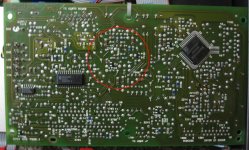
You've lost a capacitor, chase the circuit from the other transistor in the red circle from the same leg. Measure them, they likely only use 1x 10x and 100x values.
My money is on it being the same value as the cap above the number 1 in the red circle based on its size.
My money is on it being the same value as the cap above the number 1 in the red circle based on its size.
TVM for the suggestion. I will have a look and get back to you.You've lost a capacitor, chase the circuit from the other transistor in the red circle from the same leg. Measure them, they likely only use 1x 10x and 100x values.
My money is on it being the same value as the cap above the number 1 in the red circle based on its size.
I found some of these component numbers in a Philips cd931. It is in the turntable electronics. May be you can figure out something from that one although it is not identical to the Quad. PM me your E-mail adr. and I will send you the cd931 service manual.
Although it doesn't concern me dedicatedly, I'd really be interested in the outcome. Which part is missing exactly? Mind to share?
Best regards!
Best regards!
- Home
- Design & Build
- Parts
- Quad CD67 SMD identification