I want to have a schematic from this FET RIAA Preamp for removing unwanted AM reception:
https://luckyx02.de/data/documents/Aikido_Phono_Prospekt_Mail-1.pdf
Der Aikido von H.-U. Otto - Lucky's Hornpage
from the MC head amp (Pre-Pre) therefore there is to find a schematic here - go to the seventh circuit under
Aikido Tube Amplifiers
Even from the tube-version of this FET RIAA preamp there are the schematics - go to
Aikido PH-2 Phono Stage
Aikido All in One.pdf - Tube CAD Journal
https://de.scribd.com/document/150411742/Aikido-All-One
http://www.hifi-forum.de/viewthread-26-12463.html (post #16)
Thank you for upload schematics from oTTo's jFET version like to see in the attached images
Attachments
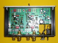

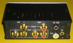
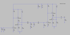
Since you have the pictures of both sides of the PCB it is not that had to make a drawing of just the first stage. Add an input filter to stop AM reception that does not interfere with the device its qualities and you are done. Yeah those old fashioned input filters, no one seems to need them these days 🙂 It was a long time ago I was busy with phono but I guess ferrite beads in the signal inputs could also be sufficient. A 100 pF ceramic disc type cap for each inputs GND to chassis might also help in case AM reception is coming via the screen of the cables. Do you use the GND screw as mounted at the back of the device?
And eh pssst... that is a switcher for PSU....
And eh pssst... that is a switcher for PSU....
Last edited:
anywhere a schematic for upload of this units under
https://luckyx02.de/data/documents/Aikido_Phono_Prospekt_Mail-1.pdf ??
according the circuit description schematic looks to those under
http://diyaudioprojects.com/Solid/JFET-Phono-Preamplifier-Kit/diy-jfet-riaa-phono-preamp.html
but with additional buffer-jFET like here
https://phonoclone.com/diy-pho6.html
an complete other approach (here from Renardson Audio) is the use of NFB RIAA network
https://www.renardson-audio.com/phono2.html
FWIW...
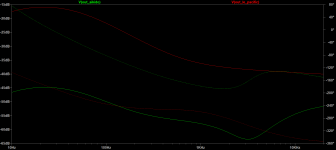
I copied that into LTspice and the simulation predicts 0.19% THD at 1kHz with 50k ohm load and 5mV RMS input (520mV RMS output at 1kHz).
I copied that into LTspice and the simulation predicts 0.19% THD at 1kHz with 50k ohm load and 5mV RMS input (520mV RMS output at 1kHz).
last URL is dead - check out the advice underanywhere a schematic for upload of this units under
https://luckyx02.de/data/documents/Aikido_Phono_Prospekt_Mail-1.pdf ??
according the circuit description schematic looks to those under
http://diyaudioprojects.com/Solid/JFET-Phono-Preamplifier-Kit/diy-jfet-riaa-phono-preamp.html
but with additional buffer-jFET like here
https://phonoclone.com/diy-pho6.html
an complete other approach (here from Renardson Audio) is the use of NFB RIAA network
https://www.renardson-audio.com/phono2.html
https://www.renardson-audio.com
go for the phono2 to the URL in post #1 under
https://www.diyaudio.com/community/...n-with-bf862-what-about-sonic-results.290389/
Last edited:
Have you tried adding some R in series to the input? Together with input capacitance it would make a first-order low-pass filter.for removing unwanted AM reception
this together with an inductivity in parallel mode as to find in the schematics in post #32+40 under
https://www.diyaudio.com/community/threads/simple-transistor-based-riaa.401265/page-2
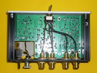
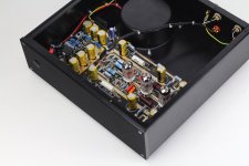
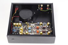
helps sometimes. But most effective solution is a very low (zero) induction connection between ground-plane of PCB and the aluminium enclosure (chassis).
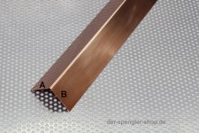
This means no usual cable wire as to see in the attached images (last attachment go to page 2 last image) because the envelope operates as RF antenna due the cable inductivity of this cable. A copper angle profile is the best solution - so I think.
https://www.diyaudio.com/community/threads/simple-transistor-based-riaa.401265/page-2
helps sometimes. But most effective solution is a very low (zero) induction connection between ground-plane of PCB and the aluminium enclosure (chassis).
This means no usual cable wire as to see in the attached images (last attachment go to page 2 last image) because the envelope operates as RF antenna due the cable inductivity of this cable. A copper angle profile is the best solution - so I think.
Attachments
Last edited:
Now I remember that I was getting AM radio interference when I was using my old phono preamp without chassis at all. The high input impedance JFET, the only one in this circuit, was acting as a detector. Maybe a preamp without tubes, jfets or jfet-input opamps wouldn't be causing any trouble for you.
- Home
- Source & Line
- Analogue Source
- Aikido "oTTo" All jFET Phono RIAA Pre-Amplifier - Schematic wanted