I am working on replacing the snubber network across the on/off switch on a Quad 22 pre-amp. For those of you who are not familiar with this piece of equipment, the on/off switch on the pre-amp serves as the on/off switch for the power amplifiers as well, connected via an umbilical cable.
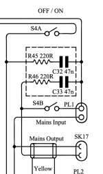
When hooked up to a variac set at 15 volts AC from the wall, I am still seeing 15 volts AC through the umbilical cable, on the other side of the switch regardless of whether the switch is on or off. Looking at the schematic more closely, I notice that the snubbers are wired in parallel to the switch.
One the one hand this makes sense; on the other hand, it seems that they would serve as a bypass for the switch altogether, so that even when the switch is off there would still be mains voltage going out through the umbilical cord to the amplifier. This would explain why I'm still seeing voltage, but it would also mean that the on/off switch is effectively useless as it would be permanently bypassed.
Is this correct? Or am I missing something? I want to make sure I have it wired correctly before proceeding.
I've attached an excerpt of the schematic for the switch and the snubber. The full schematic can be seen here:
http://www.keith-snook.info/Schematics/QUAD 22 Schematic.pdf
Attachments
When you measure with your high impedence voltmeter, this arc suppression capacitor across the power switch will behave like a high value resistor (about 67k at 50 Hz), so you read the mains voltage. When the switch is in the off position, if you body becomes in contact with the circuit, it will be hit by a 3mA worst scenario AC current. It was deemed to be safe enough back in the '60 (it is not allowed today) and you may respect this arrangement if you want to keep the device as original as possible. For safety reasons, the capacitor should then be replaced with a modern safety rated Y one, and maybe lowered in capacity. On my restorations, I relocate the arc suppression capacitor across the PT primary winding.
Thanks! I should have mentioned that I did replace it with a modern X2 rated snubber; 47nf 100R Kemet PMR209 to be precise: https://www.mouser.ch/datasheet/2/212/1/KEM_F3025_PMR209-1894099.pdf
So are you saying that when the preamp is connected to full mains I will always read the full voltage on the umbilical cord, but that there won't be enough current to the power amps for them to turn on?
That seems like a strange arrangment; I would have expected an on/off switch to isolate the circuit. I am more concerned about safety than I am about leaving it original, so if that's the case I would probably also prefer to move the RC to across the PT primary and make the switch a real on/off switch.
Last edited:
The arrangement was pretty common at the time, because it is both effective and easy to manufacture, while safety standard were more relaxed. I believe that X2 capacitors is not the correct type here; this is a Y-class capacitor application because if the capacitor fails and becomes a short, the load will be energized even when the switch is in the off position, and the fuse will not open. If you relocate it across the primary instead, then X2 is fine.
You do not even need a cap. Wire a 3-way (stairway) light circuit in your house. The 3rd wire will read 55VAC when the lamp is off. Just due to the capacitance of dozens of feet of cable and the high-high impedance of DMMs.
Hang a lightbulb or resistor on the end where the amplifier goes. Even a 7Watt incandescent will probably pull-down the stray voltage to less than a Volt.
Hang a lightbulb or resistor on the end where the amplifier goes. Even a 7Watt incandescent will probably pull-down the stray voltage to less than a Volt.
Does anyone know what the metal shield on the mains switch is for?I can only think either sheilding or safety.Would make it much easier to put new suppression caps on if it wasnt there.Ta for any advice.Also can anyone confirm the wiring?
Thanks
John
Thanks
John
Thank you sir.I forgot the wiring but pretty sure im right.Asked Quad but they are now under the control of IAG who I found less than helpful.Mains input splits into tw😵ne goes to one switch with output of that going to Yellow Quad ll which then sends back to 22 DC voltage and heater voltage.Second input goes to switch S1 then back to second main switch so that when yopu select stereo on 22 this then turns on AC supply for the blue Quad ll.Pretty sure thats correct.
- Home
- Amplifiers
- Tubes / Valves
- Quad 22 on-off switch