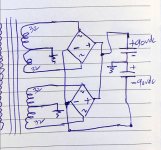
Hi guys apologies for the cruddy drawing. Can this work?
OK I know it works, I have tested it, but don't know about long term impacts. Its basically joining two secondary's in parallel isolated by a bridge rectifier.
Why? Because I have the parts for is and it can be used in a project.
OK I know it works, I have tested it, but don't know about long term impacts. Its basically joining two secondary's in parallel isolated by a bridge rectifier.
Why? Because I have the parts for is and it can be used in a project.
Attachments
it will work, as long as you use identical power traffos....
there are other ways to do it though...
there are other ways to do it though...
Yeah, that just doubles the current, not the voltage. Would be +/-45VDC.
If you want +/-90VDC, connect the windings in series, ignore the CTs, and use one FWB.
If you want +/-90VDC, connect the windings in series, ignore the CTs, and use one FWB.
Last edited:
How did you arrive at double output voltage ?
The secs in this drawing should have shown 64-0-64 not 32-0-32. My bad. The question was about connecting secs in parallel via a bridge to avoid exact matching the secondaries since any variations will cook the toroid. The joining "after" bridge gives me a 1.2v buffer for voltage variations on the secs (forward drop of the bridge is 1.2v)
In reality I have a Toroid with 12x 32v windings. (or 6 sets of 64vct)
After connecting each adjacent windings in series, I get 3 winding of 64-0-64. Which are not really usable. I will be wasting 1/3rd of the windings if I tried a dual mono config.
So I figure parallel 3 of those 64-0-64 to get a high current single supply of 64-0-64.
If there are other ways to get 90vdc from twelve 32vac secs, pls share.
The Twelve 32vac secs are in sets of 2 with center tap. So 6 sets of 64 VCT (32-0-32)
Last edited:
better if you can just make separate psu's per channel...using the same toroid with many identical windings....
If the secondaries are wound bi-filar then it should work well.
If not then one might be taking more of the load.
I try to avoid paralleling transformers if possible.
I got caught out with a SMPS transformer where I didnt wire them bi-filar enough.
The result was higher current than expected in the secondary.
If not then one might be taking more of the load.
I try to avoid paralleling transformers if possible.
I got caught out with a SMPS transformer where I didnt wire them bi-filar enough.
The result was higher current than expected in the secondary.
I don’t know if it’s bifilar. I am curious no one has alluded to the isolation accorded by the rectifiers. I am not tying the windings directly.
It’s a single core, with six center tapped secondaries. They match very well in voltages.
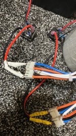
Good thing is, is has a thermal switch embedded with external leads tapped. I could use this to switch off the amp if the temperature gets warm.
It’s a single core, with six center tapped secondaries. They match very well in voltages.
Good thing is, is has a thermal switch embedded with external leads tapped. I could use this to switch off the amp if the temperature gets warm.
I don’t know if it’s bifilar. I am curious no one has alluded to the isolation accorded by the rectifiers. I am not tying the windings directly.
It’s a single core, with six center tapped secondaries. They match very well in voltages.
Good thing is, is has a thermal switch embedded with external leads tapped. I could use this to switch off the amp if the temperature gets warm.
What you did is OK, the rectifier isolates the windings,
if one is 1V less all rising current will flow from the higher voltage until the DC resistance has lowered it by 1V and the second winding starts contributing as well. It is the same for the Xformer, the sum currents, losses, flux ...
Last edited:
Ty Bansuri. Exactly what I thought.
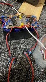
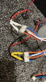
I did a quick test with loose wires to test the concept. Photos in next comment
I did a quick test with loose wires to test the concept. Photos in next comment
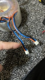
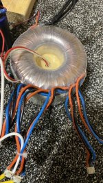
post a picture of the trafo
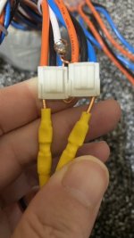
Here you go: each orange and blue wire is 64vct or 32-0-32 with black being ground.
To get 64-0-64 , I connected two sets in series. I ignored the black ground wire (not connected) and joined in series. The blue from one to the orange of other winding. This gave me my ground. The leftover orange and blue became 64-0-64. But this is not my question.
Its, can I parallel two ( or three) of these 64-0-64 groups together (via bridge recifier to single capacitor bank)
I know it works in concept. Already mocked it....
Attachments
-
 A87E9FBA-57F0-4D30-A2F9-BCDCF7CD718F.jpeg151.5 KB · Views: 78
 -
 1B609D7D-3981-4FF6-9E9F-8BBCACE30FBE.jpeg147.2 KB · Views: 81
 -
 FA29ABA5-0203-44EA-BF71-E92AF50CAFEF.jpeg133.3 KB · Views: 77
 -
 BB64FAA5-373C-4B5D-9E37-2B80611721D8.jpeg118.8 KB · Views: 74
 -
 8B038D5D-475B-4222-8BFB-C60F77144527.jpeg143.7 KB · Views: 64
 -
 52F97AD5-69D0-4357-B76C-F5E68BC33432.jpeg56.5 KB · Views: 54
 -
 508D347E-CF0F-47BE-A9EA-AFA25CBF68DC.jpeg127.3 KB · Views: 49
Last edited:
- Home
- Amplifiers
- Power Supplies
- Joining secondaries