Good day gents,
I got a mtx7801 that came in, no audio, no high current.
Power supply drive components were replaced and amp now powers up with LED 401 lit.
I have rail voltages and +/-15v on the op amps, no R-R oscillation. I replaced both 5532 and opto couplers, I noticed Q405 missing, anyone knows which transistor goes here?
Attachments

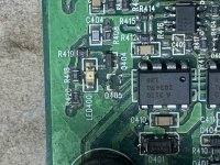
Q405 is a JFET. MMBFJ111 or SST111.
If you drive a signal into the amp, do you get drive to the input of the optocouplers?
If you drive a signal into the amp, do you get drive to the input of the optocouplers?
Had this on the back burner for some time.
I replaced Q405, this is what i have:
rail voltage,
+/-15v on opamps,
I've jumpered (bypassed) the pre amp board on the main board.
I don't have R-R oscillation.
i have 6.4v dc on speaker terminals.
I drove a strong 45hz into the inputs and I get a 7v 45hz square wave on both inputs of the optocouplers.
Attachments

One input of each optocoupler should be directly connected to ground.
If you have the tutorial, the 7801 page shows the waveforms. If you're having trouble seeing the Flash content, email me.
babin_perry@yahoo.com
If you have the tutorial, the 7801 page shows the waveforms. If you're having trouble seeing the Flash content, email me.
babin_perry@yahoo.com
I got one input pin on each coupler connected to ground.
I checked the waveforms against what I'm getting;
On the lower opamp (closest the edge of the board) I have a clean sine wave on both input and output pins for both opamps.
on the top opamp (closest the optocoupler) I have square waves on pins 1 and 7, matching the 45hz, the pulse width varies with input amplitude.
I don't have the triangle wave on pins 1, 5 and 6.
So you have the square wave on one input of each optocoupler.
If you have a square wave of 7v on one input of the optocouplers and the other input of each optocoupler is at ground, the LEDs of the optocouplers are open. Note the amplitude on the 7801 page is only about 2v.
If you have a square wave of 7v on one input of the optocouplers and the other input of each optocoupler is at ground, the LEDs of the optocouplers are open. Note the amplitude on the 7801 page is only about 2v.
I gotcha.....
I replaced both optocouplers and both opamps.
I have:
19.91v across pins 5 and 8 (optocoupler closest FETs/heatsink)
18.24v across pins 5 and 8 (optocoupler closest edge of PCB)
without audio I don't have any waveforms on either side of the optocouplers. with audio I get the corresponding square waves.
I connected a speaker to the output terminals, I have a distorted 45hz out.
Attachments
Are you now seeing the waveforms on the inputs to the optocouplers that are shown on the 7801 page?
±2v square wave on one input and ground (no signal) on the other input for the optocouplers?
±2v square wave on one input and ground (no signal) on the other input for the optocouplers?
Without audio I don't have any waveforms on either side of the optocouplers.
With audio I get the corresponding square waves.
I'm using -spk terminal for scope ground.
With audio I get the corresponding square waves.
I'm using -spk terminal for scope ground.
Last edited:
You haven't posted a square wave since post #3.
The waveform you recently posted was at the speaker terminals.
The amp is self-oscillating so it may not have any square wave until it sees a signal. Drive just enough signal into it to get it to oscillate and check the signal on the input of the optocouplers.
Are you getting rail-rail oscillation on the input of the output filter inductor?
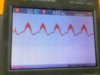
The amp is self-oscillating so it may not have any square wave until it sees a signal. Drive just enough signal into it to get it to oscillate and check the signal on the input of the optocouplers.
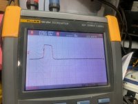
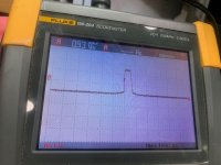
*these are the signals at the input of each optocoupler.
Are you getting rail-rail oscillation on the input of the output filter inductor?
*I don't have R-R oscillation at the input of the filter circuit.
*these are the signals at the input of each optocoupler.
Are you getting rail-rail oscillation on the input of the output filter inductor?
*I don't have R-R oscillation at the input of the filter circuit.
Attachments
You would see about 5 complete waveforms if it was oscillating. Increase the level until you see additional cycles.
I did some digging, after looking at the voltages and waveforms on both opamps:
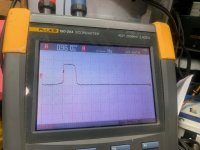
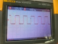
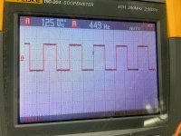
> the opamp closest the optocouplers was getting a bit more than warm to touch. I noticed there wasn't a sinewave from the out of the other opamps (pins 1 and 7) to pins 2 and 3 of this opamp, all associated components tested ok out of circuit. I replaced this opamp and jumpered the outs (pins 1 and 7) of the other opamp to pins 2 and 3. with this I got square waves at both optocoupler inputs (waveforms below)
>I moved across to the optocouplers (I have them installed in sockets) tests ok out of circuit. the optocoupler closest the edge of the PCB has a square waveform that comes and goes very quickly across pins 5 and 7. this optocoupler measures 12.6v across pins 5 and 8.
>the other optocoupler (closest the heatsink) tests good out of circuit but i don't have any waveforms across pins 5 to 8. It measures 19.85v across pins 5 and 8.
Attachments
You shouldn't have any waveform on the scope with one probe on 5 and the other on 8.
There are resistors between the output of one op-amp and the input of the other. Jumping them may not tell you much. Did you check the resistors R402 and R404?
When the optocouplers are out of the circuit, you have to jump terminals 5 and 6/7 to prevent excessive draw from the output stage.
When checking for signal on the output of the optocouplers, you have to place the black probe on 5 and the red on 6.
Doing that ^ do you see the 45Hz signal on the optocouplers when you have the 45Hz signal on their input?
Earlier, you had 18v+ across 5 and 8. Why only 12.6 now?
Where is ground on your scope photos? Generally, there is a marker but yours has 2 markers.
Is the scope on DC coupling?
- Home
- General Interest
- Car Audio
- Mtx 7801 q405?