I would like some advice please with my current amp project.
I am building a power amp with the chip LME49830 as driver stage for IRFP240/IRFP9240 mosfet quads, it's going to be used for bi-amping to drive the woofers of my speakers, each speaker has a pair of 9" woofers whose impedance @20-300Hz ranges from 3.5 to 6.0 Ohm
I already have a 1.4KVA transformer with a pair of 0-60VAC secondaries that I would like to use and it will give me rails of approx +-85VDC.
I know that in theory it is OK to feed the LME chip and the mosfets with that high voltage but I am not sure if -even with a very good but passive cooling- it will be safe with the load I intend to drive.
Please advice!
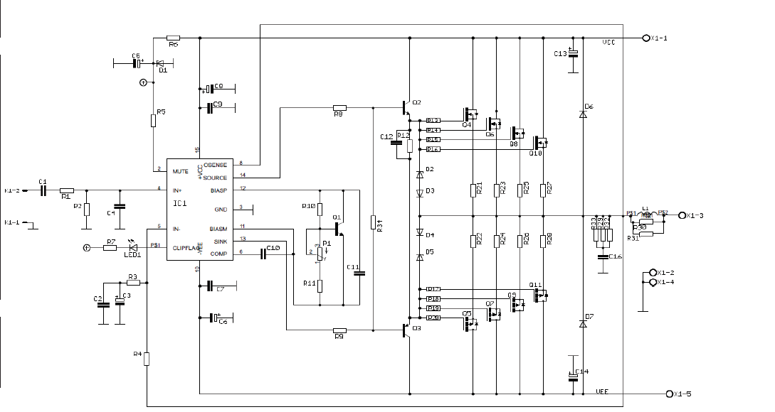
Schematic of the amp
I am building a power amp with the chip LME49830 as driver stage for IRFP240/IRFP9240 mosfet quads, it's going to be used for bi-amping to drive the woofers of my speakers, each speaker has a pair of 9" woofers whose impedance @20-300Hz ranges from 3.5 to 6.0 Ohm
I already have a 1.4KVA transformer with a pair of 0-60VAC secondaries that I would like to use and it will give me rails of approx +-85VDC.
I know that in theory it is OK to feed the LME chip and the mosfets with that high voltage but I am not sure if -even with a very good but passive cooling- it will be safe with the load I intend to drive.
Please advice!
Schematic of the amp
Last edited:
The last link is to a diyaudio.com thread
From 2014
Your schematic uses parallel transistors.
Go for higher powered single transistors.
Easier to match
Ground connections are important.
From 2014
Your schematic uses parallel transistors.
Go for higher powered single transistors.
Easier to match
Ground connections are important.
My mistake, I haven't made it clear that except the 1.4KVA power transformer I mention above I already have amplifier pcb boards, LME49830 chips, IRFP240/IRFP9240 mosfets and the heat sinks for building this amp.
If I've understood right you suggest that in order to use +-85V rails I need to replace the chosen IRFP240/IRFP9240 mosfets with other higher power ones, what would these be?
The 2SK1530/2SJ201 pair that is also used in many designs I've seen around are of the same power as the IRFPs.
The only solution I see is replacing LME49830 with LME49810 and the IRFPs with the BJTs 2SC5200/2SA1943 but this would cost me about the same as getting a new 800VA transformer with dual 0-50VAC secondaries which will give me +-70V rails and put me in the safe zone.
Last edited:
The only chance to recycle your pcbs is to reduce rail voltages.
2SC5200/2SA1943 have bad SOA if used with such high voltages. This is a no go.
BR, Toni
2SC5200/2SA1943 have bad SOA if used with such high voltages. This is a no go.
BR, Toni
Yes, all the voices in my head tell me to go for a new transformer but I had to ask just in case there was something else to be done that I couldn't think of.
I wouldn't like to change from mosfets to BJTs too.
I wouldn't like to change from mosfets to BJTs too.
Fine! The SA2012 using 3 pair IRFP240/9240 running with up to +/- 70 would give a good 8R/200W amp. This was the design goal in the early 2010 years.
BR, Toni
BR, Toni
I have your SA2012 PCBs finished populated with their components too, the only reason I chose to use the ones I posted above is the extra pair of IRFPs that I hope it will give me the extra something for the use of the amp to drive pairs of 9" woofers.
What astx said.
Including keep the MosFets, forget Bipolars here, use driver IC as intended.
Good luck with your project.
Only point that worries me is:

Those are 4 ohm woofers, so use them in series for 8 ohm per pair.
Including keep the MosFets, forget Bipolars here, use driver IC as intended.
Good luck with your project.
Only point that worries me is:
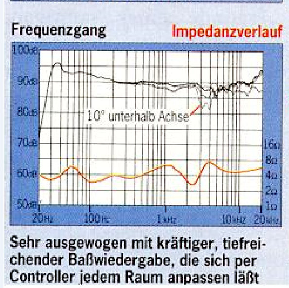
which makes me fear:pair of 9" woofers whose impedance @20-300Hz ranges from 3.5 to 6.0 Ohm
Those are 4 ohm woofers, so use them in series for 8 ohm per pair.
Thanks JM, I'll go for a new trafo with dual 0-50VAC secondaries, as for the woofers they are in parallel and not 4Ohm each, speaker's impedance drops only down to 3.5/3.2Ohm @30 and 100Hz according to the graph.
Last edited:
Do you have component list for this scheme?
I would like some advice please with my current amp project.
I am building a power amp with the chip LME49830 as driver stage for IRFP240/IRFP9240 mosfet quads, it's going to be used for bi-amping to drive the woofers of my speakers, each speaker has a pair of 9" woofers whose impedance @20-300Hz ranges from 3.5 to 6.0 Ohm
I already have a 1.4KVA transformer with a pair of 0-60VAC secondaries that I would like to use and it will give me rails of approx +-85VDC.
I know that in theory it is OK to feed the LME chip and the mosfets with that high voltage but I am not sure if -even with a very good but passive cooling- it will be safe with the load I intend to drive.
Please advice!
Schematic of the amp

- Home
- Amplifiers
- Chip Amps
- 85V rails at Lme49830 IRFP240/IRFP9240 amp