Who can upload schematics ?
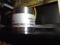
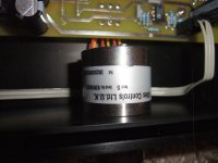
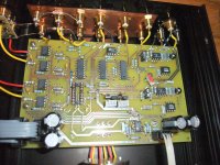
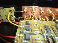
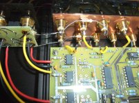
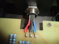
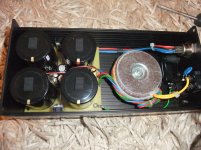
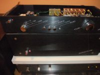
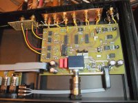
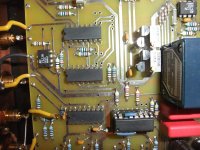
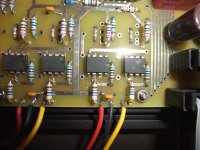
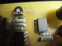
In the attachment various images around the PCB and outdoor power supply
P&G website is dead - go to
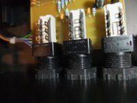
Penny + Giles - Rotary Potentiometer
In the attachment various images around the PCB and outdoor power supply
P&G website is dead - go to
Penny + Giles - Rotary Potentiometer
Attachments
-
 DSCF7016.jpg1,008.7 KB · Views: 530
 -
 DSCF7030.jpg979 KB · Views: 506
 -
 DSCF7028.jpg983.2 KB · Views: 494
 -
 DSCF7026.jpg1,023 KB · Views: 504
 -
 DSCF7024.jpg1 MB · Views: 576
 -
 DSCF7022.jpg992.6 KB · Views: 307
 -
 DSCF7020.jpg1,010.6 KB · Views: 275
 -
 DSCF7018.jpg979.2 KB · Views: 282
 -
 DSCF7036.jpg1,023.3 KB · Views: 273
 -
 DSCF7056.jpg979.7 KB · Views: 274
Last edited:
Standard Version with Alps RK27112 (Alps Blue) for Volume Attenuation
even differences also on main board
even differences also on main board
Attachments
-
 DSCF6989.jpg1,002.2 KB · Views: 237
 -
 DSCF6991.jpg1 MB · Views: 220
 -
 DSCF6993.jpg1 MB · Views: 201
 -
 DSCF6995.jpg1,014.2 KB · Views: 183
 -
 DSCF6997.jpg1,011.3 KB · Views: 167
 -
 DSCF6999.jpg990.2 KB · Views: 170
 -
 DSCF7002.jpg1,002 KB · Views: 180
 -
 DSCF7010.jpg986.2 KB · Views: 210
 -
 DSCF7004.jpg979.5 KB · Views: 186
 -
 DSCF7006.jpg1,007.6 KB · Views: 188
I myself hadn't heard many pre-amp devices in comparison. Numerous users I know and who have already had many different pre-amps for listening tests are convinced of this and had therefore decided on this brand - mostly with the volume control from P&G.
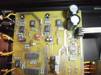
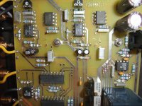
on page 1 of the attached PDF you will find both the versions with and without the CMOS switching IC in the socket.
*I is according image No 5 in post #1
*II is according image No 5+6 in post #2
And on page 2 you will find the modification with additional two outputs by serial resistors for sub-woofer and for an additional mid bass power amp rail (was in genuine condition none variable buffered outputs for two tapes). The serial resistors avoid influences on the high frequencies of the capacitance of long signal wires.
The question is, what OPA types are in use for the output driving ?
Last edited:
When was this made? Nineties?
The one obvious exceptional feature is the massive copper plate. Most of today's "grounding boxes" are based on the same non-engineering concept and i am inclined to believe it improves perceived sound quality.
The absence of regulators will make it sound different to a lot of standard designs but the actual implementation seems too basic.
As for the topology...yawn. A buffered potentiometer, like that famously copied MBL. Not convinced it's an essential feature for better sound.
Cannot believe it sounds better than the battery powered ASRs.
Date of manufacturing is between 1998 and 2007 - so I think.
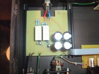
Regulators are in use, but are implemented in the outdoor power supply and not in the preamp unit - go to last two images of post #1
Regulators are in use, but are implemented in the outdoor power supply and not in the preamp unit - go to last two images of post #1
I think that this concept of All-together grounds @ input rca-s is wrong. With switching only hot wires with selector, there are N-1 ground loops even when other devices are OFF.
Because of existing connection via chasses groing pin 220V power socket. That most lightly components have, and again most chances that they chasses ground pins are connected to chasses of every device connected in the system.
.
I thik that for each channel, booth lines hot and ground, should be disconnected with selector. To have only ONE connection from selected device in the system. Not all chasses grounds, from devices connected via cables...
.
That is the common say mistake in the preamp zone. Does not matter how expencive they are... 🙁
.
Also dont believe in "huge" capacitor banks in preamlifier. Rather small C and Big power transformer...
Last edited:
- Home
- Source & Line
- Analog Line Level
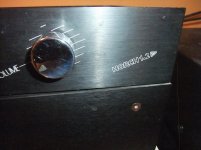
- Horch 1.2 P&G - one of German's best sounded Pre-Amplifiers. Schematic wanted