Some may be surprised, battery bias by a single cell is not a new idea. Was common in many receivers of the 1930s. But not in the cathode lead where it would be on charge all the time the circuit is on.
So install a Triple 'A' NiCd at the bottom of the grid resister, polarity such that the tube is biased into its operating region. Under normal operation current in the battery will be essentially zero, should last a normal shelf life.🙂
So install a Triple 'A' NiCd at the bottom of the grid resister, polarity such that the tube is biased into its operating region. Under normal operation current in the battery will be essentially zero, should last a normal shelf life.🙂
Attachments

If you put the battery in series with the signal:
+ connected from the RC coupling; - connected to the grid stopper; and the grid stopper connected to the grid . . .
Then, the only time the battery will see significant current is if the signal voltage causes grid current. And that current will trickle 'charge' the battery, but only during maximum signal (that draws grid current).
Works great, if you like that sort of thing.
If you put the battery in series with the signal:
+ connected from the RC coupling; - connected to the grid stopper; and the grid stopper connected to the grid . . .
Then, the only time the battery will see significant current is if the signal voltage causes grid current. And that current will trickle 'charge' the battery, but only during maximum signal (that draws grid current).
Works great, if you like that sort of thing.
------------------------------------------------------------------------------------------
Where did you ever see the connexion to a bias battery that way? Pls shew us an example & ID from where, THX🙂
I have built two stage single ended amplifiers, to bias the output tubes (2A3 and 300B).
They did work well.
9.5V x 5 = 47.5V (the 9V batteries are about 9.5V); and 9.5 x 6 = 57V.
You may have to adjust the series resistor in the B+ supply that connects to the filter cap that powers the output transformer B+ lead, in order to get the plate current you want.
If nobody reading my Post # 3 can engineer and build a practical tube amplifier that makes a series bias battery work, then I will not give away any more details.
Or, as an exercise for all the software simulator fans out there, just build a simulation model, and vary the B+.
Actually I want to use a 6.3v @1.5A power transformer with Belleson low voltage regulator for negative 1.2v.
Superpower SPLV Positive Superpower Regulator
I have 2 x 6.3v power transformer sits here for years for nothing.
Any thoughts??
Superpower SPLV Positive Superpower Regulator
I have 2 x 6.3v power transformer sits here for years for nothing.
Any thoughts??
I think you're about to invent fixed biasing...Any thoughts?? Is that a good idea?
Batteries & Tubes
All the things 6A3SUMMER mentioned, even the trickle charge. But why use a power supply if you're talking about batteries? Thats just a fixed bias Amp off the power supply. Maybe a setup where the battery is put on charge when the Amp is off? Or an Arduino that computes if a charge is needed and does it when Amp is off maybe once a year. You'd get about 5000 recharges, a lifetime.
All the things 6A3SUMMER mentioned, even the trickle charge. But why use a power supply if you're talking about batteries? Thats just a fixed bias Amp off the power supply. Maybe a setup where the battery is put on charge when the Amp is off? Or an Arduino that computes if a charge is needed and does it when Amp is off maybe once a year. You'd get about 5000 recharges, a lifetime.
Last edited:
Location of In Circuit Bias Battery
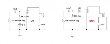
From the description given by 6A3summer this seems to be the connexion he would use. Last thing the grid needs is an extra lump of capacitance to pick up stray electric fields. And to add to the Miller effect & the possibility of positive FB. The battery hardly needs charging in the normal position, it will simply die of old age.😀
From the description given by 6A3summer this seems to be the connexion he would use. Last thing the grid needs is an extra lump of capacitance to pick up stray electric fields. And to add to the Miller effect & the possibility of positive FB. The battery hardly needs charging in the normal position, it will simply die of old age.😀
Attachments
jhstewart9,
Correct, the right hand schematic gives the essence of the battery bias circuit.
It is nice that Windcrest77 referred to John Broskie's paper.
The grid stopper I mentioned does help when using series battery bias.
Nothing on this earth lasts forever, except our souls.
All batteries eventually die, whether charged, discharged, or just sitting there over time.
And so do electrolytic capacitors.
Conecting a bias battery from the bottom of the grid leak resistor to ground, the signal voltage will cause current to flow into the battery, and current to flow out of the battery, even if there is zero capacitance in the circuit.
Putting a series battery to the grid, the discharge current is only from the Miller Effect capacitance. The charge current is only from the Miller Effect capacitance, and/or if you draw grid current (not recommended for RC coupling, the bias shifts), then from the grid current.
Take an alkaline 9V battery, mount it with a double sticky tape to a chassis, and measure the capacitance from the + or - lead to the chassis.
Gee, that is capacitance, so is wiring, so is the Miller Effect.
Connect to a wire that is in free space, that has capacitance too.
A driver can be designed to drive capacitance, what a concept!
I design my amplifiers to have less than 100uV hum, so much for hum pickup by the battery.
Positive feedback is not limited only to the capacitance of a battery.
Wiring can be another form of positive feedback.
How many on this forum have to be told to re-locate their wiring to get their amplifier to stop oscillating.
The purpose of wiring the battery in series was not to charge the battery. Drawing grid current was not recommended.
The very small charge and discharge currents to drive the Miller Effect Capacitance will essentially give the battery the same lifetime as it would sitting on the shelf.
Good alkaline batteries have very good shelf life.
There is not perfect topology, all of them have some tradeoffs.
Last edited:
Nothing on this earth lasts forever, except our souls.
Mine won't!!🙂The Earth won't either, give it about 5B years by current estimates, about the same time the Sun quits.😱
As mentioned often by Alfred E Neuman, 'What, Me Worry'!
Mine won't!!🙂The Earth won't either, give it about 5B years by current estimates, about the same time the Sun quits.😱
As mentioned often by Alfred E Neuman, 'What, Me Worry'!
Our immortal souls are now on this earth.
Later, they may be somewhere else than on earth.
Just my opinion, and my belief.
Later, they may be somewhere else than on earth.
Just my opinion, and my belief.
John Broski
I followed John Broski's blog for several years back in the day. John beat the circuits to death & tried everything possible. When JB was finished there was little for others to add. I wonder how many of these were ever built?
In the Batteries & Tubes blog I see nothing more than a 3V battery bias mentioned, nothing that would satisfy a power amplifier stage. So 3V from a 2032 button battery would be OK in many circuits. But not if it was in the cathode.
One of John Bs rants is attached, I firmly believe in this on!😀
Attachments
I guess we did find something that John Broskie did not try, correct?
Battery bias for output tubes.
Given a small chassis, a power transformer with fixed 700VCT B+ and 6.3V filament windings,
and a single 6.3V filament input triode, and 2.5V 2A3 or a 5V 300B filaments, and no other transformer taps, a choke input filter for the B+, in order to preserve B+, battery bias is a reasonable option.
Some instead would just use a small switcher supply to give the output tube bias voltage (fine for those that want to do it that way).
Others would tack on a second transformer and diodes, and capacitors for the output tube bias voltage (fine for those who want to do it that way).
I made an executive decision, and used battery bias, because I wanted to do it that way.
I hope that is acceptable.
Last edited:
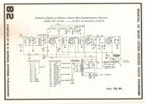
That is a good description of back-biasing. Quite a few 1930s radios used that circuit, here is one example. Large value electrolytic caps were either unavailable or expensive. A common way to improve the ripple problem was a capacitor in parallel with the filter choke, broadly resonant at the ripple frequency. In this one the choke is the loudspeaker field coil.🙂
Attachments
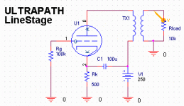
Please post the schematic showing your idea, not one showing something else.My friend just share the idea with me about replacing cathode resistor with negative 1.2v supply. And the Ultrapath Capacitor would be much smaller. And absolutely free of noise form the power supply to cathode.
Any thoughts?? Is that a good idea?
I do not know what you mean by
and not too sure you do.replacing cathode resistor with negative 1.2v supply
An image will be way clearer than words.
So please do.
This thread has been wandering because of your lack of clarity.
- Home
- Amplifiers
- Tubes / Valves
- Negative Supply for Ultrapath??