Hi All,
I'm not sure if this is expected behavior given the actual DC Offset measured at the speaker terminals is stable at 0-1mV Left and 0-3mV Right, after warming up.
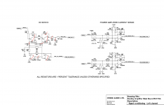
What I can't figure out is why the output from the DC Servo (U1 pin 8) is 50-150mV (it rises over several minutes) on the Left Channel, and (U101 - pin 8) is a steady 3mV on the Right Channel. Which channel is expected behavior? Or is this type of discrepancy expected due to component tolerances?
I've marked all the components I replaced in red (on both channels).
I do not understand how to isolate this issue with all the feedback loops. Am I correct in understanding that the computer on the Input Board is adjusting the dc offset (somehow) according to the value of U1(8) :ANA DC OFFSET?
Some other voltage readings.
C18 (across) - 19 mV
C118 (across) - 43 mV
C2 to ground - 80 mV
C102 to ground - 30 mV
The Idle voltage is equally stable on both channels around 21.5mV.
Any guidance is appreciated.
I'm not sure if this is expected behavior given the actual DC Offset measured at the speaker terminals is stable at 0-1mV Left and 0-3mV Right, after warming up.
What I can't figure out is why the output from the DC Servo (U1 pin 8) is 50-150mV (it rises over several minutes) on the Left Channel, and (U101 - pin 8) is a steady 3mV on the Right Channel. Which channel is expected behavior? Or is this type of discrepancy expected due to component tolerances?
I've marked all the components I replaced in red (on both channels).
I do not understand how to isolate this issue with all the feedback loops. Am I correct in understanding that the computer on the Input Board is adjusting the dc offset (somehow) according to the value of U1(8) :ANA DC OFFSET?
Some other voltage readings.
C18 (across) - 19 mV
C118 (across) - 43 mV
C2 to ground - 80 mV
C102 to ground - 30 mV
The Idle voltage is equally stable on both channels around 21.5mV.
Any guidance is appreciated.
Attachments

Last edited:
Maybe you are over thinking it 🙂
The DC servo output will change as is needed to maintain the main amplifier output at zero volts. It is simply correcting changes and drift that occur with temperature in the main amplifier.
If that is what you mean then that is normal. One channels main amplifier just happens to be better balanced than the other, that's all.
Probably lol 🙂
Ok so then the amp is running smoothly 🙂.
Thanks for the help.
Ok so then the amp is running smoothly 🙂.
Thanks for the help.
