Put together seems pretty self explanatory as no detailed direction is offered from Ghent or Parts Express.
I'm left with 2 questions:
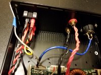
The harness for xlr connection has a shielded cable at one end which has 2 wires and a surrounding stranded shield for the neutrik connect, 1,2,and 3 ground, positive, negative respectively. However, at the other end of the jst harness there is a lengthy grey wire. Would this connect to the star chassis ground or ground tab hanging off the neutrik connect?
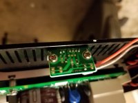
Also the kit didn't come with an led bulb and I'm wondering where on the snall dimmer led pcb board does the two leg of the led bulb get soldered to? There are several through holes open there.
Thanks in advance.
I'm left with 2 questions:
The harness for xlr connection has a shielded cable at one end which has 2 wires and a surrounding stranded shield for the neutrik connect, 1,2,and 3 ground, positive, negative respectively. However, at the other end of the jst harness there is a lengthy grey wire. Would this connect to the star chassis ground or ground tab hanging off the neutrik connect?
Also the kit didn't come with an led bulb and I'm wondering where on the snall dimmer led pcb board does the two leg of the led bulb get soldered to? There are several through holes open there.
Thanks in advance.
Watching this. I have been looking at the Ghent and icepower combo also. let us know how it sounds.
Do you not have a circuit diagram or schematic from the icepower to see what that pin is labelled for?
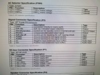
Tuberoller, I suggest you look at the official ICEpower 500ASP datasheet -
https://icepower.dk/download/2402/
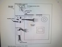
I suggest you ensure proper earthing, by making sure the aluminium base of the 500ASP makes good electrical contact with the floor of the Ghent case - you should scrape away some anodising from the floor of the case where your 3mm screws attach amp base to floor.
And obviously do the same thing with the attachment from the AC connector's earth pin to the case floor.
Once done, check continuity between AC connector earth pin and amplifier base - there should be zero resistance. You can also check continuity between AC connector earth pin and pin 3 of the JST audio harness (P2) - this might be zero ohm, or it might be 10kohm, depending on whether ICEpower decided to put a resistor between AGND and earth.
https://icepower.dk/download/2402/
From the diagram on page 4 it appears that wire has no connection (!) so maybe it's just a spare wire?at the other end of the jst harness there is a lengthy grey wire
I suggest you ensure proper earthing, by making sure the aluminium base of the 500ASP makes good electrical contact with the floor of the Ghent case - you should scrape away some anodising from the floor of the case where your 3mm screws attach amp base to floor.
And obviously do the same thing with the attachment from the AC connector's earth pin to the case floor.
Once done, check continuity between AC connector earth pin and amplifier base - there should be zero resistance. You can also check continuity between AC connector earth pin and pin 3 of the JST audio harness (P2) - this might be zero ohm, or it might be 10kohm, depending on whether ICEpower decided to put a resistor between AGND and earth.
You may find there's a tiny surface-mount LED on your board, which is barely noticeable.Also the kit didn't come with an led bulb
Thanks Linuxfan,
I think the bulk of my questions are answered and am about ready to fire it up ;-)
Although, the "spare wire" will remain a mystery. I suppose it will be coiled up and tucked away until further notice.
Thanks again🙂
I think the bulk of my questions are answered and am about ready to fire it up ;-)
Although, the "spare wire" will remain a mystery. I suppose it will be coiled up and tucked away until further notice.
Thanks again🙂
Still pondering.... I wondered if this could be a roundabout way of grounding pin1 to chassis. There is another sanded screw hole on the corner opposite of the iec. Does it matter how far away a chassis ground is from the originating point? Most diagrams have a short immediate grounding location. Is is it better to have one star ground or are multiple allowed? Is this then what may create a ground loop?
Thanks again🙂
Thanks again🙂
Although, the "spare wire" will remain a mystery. I suppose it will be coiled up and tucked away until further notice.
Thats what I did to mine in a a pair of ASP1000 ;-)
//
I addressed this issue in another forum thread recently -I wondered if this could be a roundabout way of grounding pin1 to chassis ...
https://www.diyaudio.com/forums/class-d/364960-3e-tpa3251-lrs-350-36-hifi2000-build.html#post6463715
Summary: if your amplifier's AGND is not electrically contiguous with its metal mounting points, then a common choice for earthing AGND is at the point where your audio input connector meets the chassis ...
but if your amplifier's AGND is electrically contiguous with its metal mounting points, AGND is already earthed (once mounted) so there's no need to earth again at the audio input connector.
To prove this: with your current ICEpower 500ASP build, check continuity from pin 1 of the XLR connector to the earth pin of your AC connector - it should confirm electrical continuity (either zero ohm or 100kohm) and nothing more is required.
- Home
- Amplifiers
- Class D
- ICEpower ASP500 kit from Ghent and module from PartsXpress