I decided to dive into the world of tube amplifiers by building one. I researched how they work, and found a schematic I would use as a starting place. I chose the AC-568 bassman, but I had some changes I wanted to make. I gave it a potentiometer on the tone slope resistor, added a mid control, and gave it a class A power amp. I only used the bass channel, and the input with a resistor going to ground. I added a 4th gain stage too, simply because I still had half of a 12ax7 available. The first time I turned it on a few things happened..
A few hours with the oscilloscope narrowed it down to the 3rd gain stage, and more specifically the tube. there was signal through the whole line until the plate. I moved the wire on the screen of the 3rd gain stage to the screen of the 4th, eliminating the 3rd stage if I'm correct. I tried it again and now I just get really loud hum, and no signal. I haven't looked at it with the oscilloscope yet, but I can't quiet the hum with the ground switch or the volume. My best guess is that I have a ground problem, but that's just a guess. This is the schematic I drew, I know it's a mess but better than nothing. Bass amp prototype by adhehl | Upverter Thanks in advance for any help, sorry for the long post!
- It hummed very loudly
- the guitar signal was patchy, thin, and very distorted
- It made a bit of a "pop" from the speaker and went quiet
A few hours with the oscilloscope narrowed it down to the 3rd gain stage, and more specifically the tube. there was signal through the whole line until the plate. I moved the wire on the screen of the 3rd gain stage to the screen of the 4th, eliminating the 3rd stage if I'm correct. I tried it again and now I just get really loud hum, and no signal. I haven't looked at it with the oscilloscope yet, but I can't quiet the hum with the ground switch or the volume. My best guess is that I have a ground problem, but that's just a guess. This is the schematic I drew, I know it's a mess but better than nothing. Bass amp prototype by adhehl | Upverter Thanks in advance for any help, sorry for the long post!
 Moved to Instruments & Amps per forum policy. Please note the forum subheaders
Instruments and Amps Everything that makes music, Especially including instrument amps.
Please post project documentation here.
Good luck!
Okay, will do. Thanks for the advice! Can I just solder the wire from screen 3 to the pin on the 4th plate, or should I de-solder that too and add some heat shrink tubing?
The power supply is drawn wrong, D7 burns out immediately. This is the AC heater line.
the upper secondary winding needs to be connected to gnd like the middle one
D8 R32 wrongly connected
There is a high DC- current through T1, it will saturate and heat up
T1 needs a second primary with a current sink to compensate for the DC.
Sorry I do not think it will ever work as imagined.
the upper secondary winding needs to be connected to gnd like the middle one
D8 R32 wrongly connected
There is a high DC- current through T1, it will saturate and heat up
T1 needs a second primary with a current sink to compensate for the DC.
Sorry I do not think it will ever work as imagined.
R15 R16 are specced "1500k". Like a thousand times higher than usual.
Assuming it really is 1500...... you have four stages at gain of about 50 each. 50*50*50*50 is 6 million. Tonestack loss is at least 6:1, so pencil gain of a million. No details around the output stage except some show-off cap voltages, so pencil 40V peak grid drive. This make input-jack sensitivity about 40 micro-Volts, a THOUSAND times more gain than classic guitar amps.
The Fender AA-Champ plays well with just one 12AX7. You have WAY too much gain for a "first dive".
Attachments
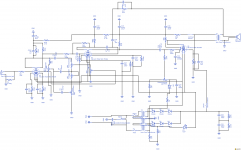
I couldn't find the "lamp" symbol, so I used the led as a stand in. I also decided to go take a diode off both half's of the rectifier so voltage would be usable with my transformer selection. I take it you're talking about the secondary winding on the power transformer? If so its a classictone 40-18019, and I'm reasonably certain I have it hooked up properly, even though it may not be in the schematic. I couldn't find that specific transformer in the program, so I again used it as a stand-in, and had the spec sheet next to me as I wired it. D8 and R32 are now non existent as I went to a cathode bias system, and the voltage is correct. Where exactly is the high DC current coming from? The power tube plate? Thanks for looking at the schematic, I know it's not the easiest to read.
R15 and R16 are my bad, they are 1.5K. I think I'm going to take out the 4th gain stage as well. Youre absoluyely right, my "bass" amp has no reason to be high gain, especially as a first project.
R15 and R16 are my bad, they are 1.5K. I think I'm going to take out the 4th gain stage as well. Youre absoluyely right, my "bass" amp has no reason to be high gain, especially as a first project.
I repeat: the AA764 has enough gain for most purposes, and when I built one last it was hard to make stable even though this is not a "high gain" amp. You do not need four stages unless you have LOTS of attenuation between stages. You probably do not need three.
It is also an excellent drawing.
SE amps have never been satisfactory for "bass". Even my 13-17 Watt 6550 "Champ". I suspect it could work with a bass horn as big as a room; but that is inconvenient. Also the output iron size/weight gets out of hand. I'm not saying "stop"; but you may end up as a guitarist to put the SE amp to work.
Attachments
Sorry for the confusion, the 3rd gain stage has already been bypassed, so removing the 4th would leave me with 2. With my chassis design it isn't very difficult to get to the tube sockets, so I almost want to just give it a try with two and see what happens. Going down to one if I don't like it would be easy enough. Designing and building this has been a high school music lab project, so I feel like I could even write that off as an experiment.😀 My only gripe about making this a guitar amp rather than bass is that I already bought a 12 inch bass speaker.(also less common, I know) It wasn't super expensive though, so I'm happy to do anything that'll salvage the project.
Okay, I don't like making so may posts in a row, but I think I'm on the right track. I added a jumper from the Plate pin of the second gain stage to the plate of the 4th. As stated before, the grid is disconnected on the 3rd stage, so I bypassed the whole second 12ax7. I hooked everything up, and To my amazement it worked. Ish. I have amplified signal, but its the volume I would expect from a one watt amp, not the 15 watt amp I built. I started with the guitar, and it was very clean, even with 2 gain stages. When I switched over to the bass it was much more distorted, especially on the low end. I don't mind this as much as the volume though. The power tube was starting to red plate too, so I'll have to change the bias resistor at some point I think. Thanks everyone for the suggestions so far, it's helped a lot!
I think if you just connected the plate of V2 to the plate of V4 without changing anything else, you'll find you have put the 100k plate resistor of V2, R9, basically in parallel with the 47k plate resistor of V4, R19 (with some complications around R10 and R20, but you can roughly consider them paralleled). 100k||47k ~= 32k, so that's a small plate resistor and will be leaving V2 without much gain (it can't easily pull the voltage down because there's too little resistance between its plate and the power supply). The best thing to do is to get *just* the things you actually want (R9 and C14) connected directly to the plate of V2, without connecting to V4's plate or its plate resistor. That may fix your volume problem.
Regarding your question about negative feedback: I think currently you actually do have negative feedback because it's connected to the grid of V4, which is not entirely removed from the circuit and is still being driven by the feedback signal! Once you get the plate of V4 truly disconnected from the signal path, you'll need to move your negative feedback loop (the leg of C18 that currently connects to the V4 grid) to the grid of V2.
Regarding your question about negative feedback: I think currently you actually do have negative feedback because it's connected to the grid of V4, which is not entirely removed from the circuit and is still being driven by the feedback signal! Once you get the plate of V4 truly disconnected from the signal path, you'll need to move your negative feedback loop (the leg of C18 that currently connects to the V4 grid) to the grid of V2.
Last edited:
Is your output tube a 6L6, btw? You mentioned you planned a 15W amp, which I think would be at the very high end of what's possible for a single 6L6 in class A.
I think if you just connected the plate of V2 to the plate of V4 without changing anything else, you'll find you have put the 100k plate resistor of V2, R9, basically in parallel with the 47k plate resistor of V4, R19 (with some complications around R10 and R20, but you can roughly consider them paralleled). 100k||47k ~= 32k, so that's a small plate resistor and will be leaving V2 without much gain (it can't easily pull the voltage down because there's too little resistance between its plate and the power supply). The best thing to do is to get *just* the things you actually want (R9 and C14) connected directly to the plate of V2, without connecting to V4's plate or its plate resistor. That may fix your volume problem.
Regarding your question about negative feedback: I think currently you actually do have negative feedback because it's connected to the grid of V4, which is not entirely removed from the circuit and is still being driven by the feedback signal! Once you get the plate of V4 truly disconnected from the signal path, you'll need to move your negative feedback loop (the leg of C18 that currently connects to the V4 grid) to the grid of V2.
Okay, that makes sense. I'll see what I can do, and if it helps. Also, yes this was intended to be a 15W Class A 6L6GC amp. That's the output I estimated would be possible, so that's what I bought for the output transformer. I wanted the wattage more for head-room than anything though, so less will be fine. The power tube voltages were well within the limits on my spec sheet before I started removing gain stages, but I'll definitely check again when i fix the power tube bias.
Update: Volume problem solved! The amp is now long enough to make my parents upset, so that's good enough for me! with guitar its nice and clean if I play normal, and if I dig in a little it breaks up really nicely. Now time to fix the bias problem. Thanks to everyone who has helped, I obviously still have much to learn!
- Home
- Live Sound
- Instruments and Amps
- Home brew tube amp problems