i acquired a bunch of tubes and transformers a couple years ago and have just started going through them. i found 3 6gw8 tubes. i have a transformer that can make 250 volts for the pentode plate and i found a couple line output transformers that can be wired in series with the secondaries in parallel to make an effective 7000 ohm primary when connected to some scavenged 8 ohm speakers connected in series to make a 16 ohm secondary load. i also have an old 3w thordarson output transformer that's 2000:3.5 that should reflect about 8000 ohms on the same 16 ohm speaker setup. thoughts on which will work best?
i found the schematic at https://www.thecolonel.id.au/web_images/6GW8 circuit a.jpg and didn't understand why they put 200 volts on the grid and use the screen grid to control the signal? i'm also considering adding an extra gain stage using 12at7 or possibly a 955 tube (i have many other options but don't know what would be best).
can anyone make suggestions?
View attachment 906572
Last edited:
He hasn't put the signal on the screen. He's drawn the symbol incorrectly. If you check the data sheet, you will see that pin 8 is the control grid, not the screen.
I'd recommend setting up the line output transformers, and set up the existing schematic circuitry and then tweak it for ok operation and see how loud that is with your guitar and available speakers. Ie. defer any need for an extra gain stage for now.
There is no feedback to reduce gain. The input triode seems to be biased a bit hot, which may affect the gain, so 1.8k cathode may be better and get that stage a bit more centre-biased.
You should really measure your PT winding resistances, and use PSUD2 to confirm what filter capacitor size you can go up to.
There are a few set up variables with the output stage, including screen voltage and filter cap, idle bias current. and speaker loading impedance. Those variables can noticeably change the output power and distortion characteristics.
I think you have to evaluate if your transformers can handle a DC current for SE, or at least describe them a bit for us to help. That impedance sounds high for a line transformer. What is the Thordarson like exactly? If you have 3 tubes, you can do SE or PP to match what one of those transformers can do for you.
The thorardson is a model 24s53. The power transformer I picked up at a hamfest. It's heavy enough for me to think it can do 50 or 60 ma fairly easily if it smokes, I'll buy a new one.
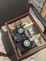
I haven't spent a penny on this amplifier yet. It's all made of spare parts I had lying around my shop. I'm inclined to experiment a little bit while I do this as I find it entertaining. I think I'm going to add one more amplification stage, probably using a 955 tube to minimize the load on the power transformer.
I haven't spent a penny on this amplifier yet. It's all made of spare parts I had lying around my shop. I'm inclined to experiment a little bit while I do this as I find it entertaining. I think I'm going to add one more amplification stage, probably using a 955 tube to minimize the load on the power transformer.
Power transformer winding resistances...
175 volt secondary, 18 ohms.
Primary, 5.4 ohms
7 volt winding, 1.3 ohms
175 volt secondary, 18 ohms.
Primary, 5.4 ohms
7 volt winding, 1.3 ohms
Sorry, I forgot to mention, with the line transformers, I would be connecting the 16 ohm speaker to the 4 ohm secondaries in parallel with the primaries in series.
PSUD2 can't easily sim a hybrid bridge, but it is likely the 6X4 ratings won't get exceeded for 47uF and up to 70mA output load.
My transformer puts out 175vac. With solid state diodes and a capacitor I can get close to 250vdc. If I use a 6x4 I'm down 30 volts to 220vdc. I don't think I can get close to the 268v on the schematic with a tube rectifier.
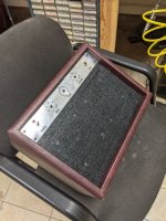
here's where i'm at. i've simulated the power supply and added a stage using a 955 tube. can someone check my work? i'm not sure about the 955 plate resistor. also, here's what the amp looks like so far....
Attachments
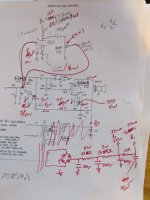
The 955 is likely to need a higher plate load resistance, perhaps circa 220k, and the bias tweaked so the idle plate voltage is circa 100V for a 150V B+ for that stage, so the cathode resistance may be circa 5V/0.5mA = 10k. I don't see any benefit in running high mA through that stage, so its B+ could be pushed higher than 150V.
The PT secondary CT should connect direct to first filter cap neg terminal, and that neg term connect direct to the next cap neg terminal, etc. Only the B+ stage neg terminal should then go to circuitry 0V, and then to chassis as a single link.
You may get hum from using such a large first filter cap (200uF) if you aren't very careful of layout and wiring.
You may need to mechanically de-couple the valve sockets and the valve socket framework from the chassis if microhpny is noticeable, as well as tube roll.
I saw my mistake and changed the plate resistor to 250k and the cathode resistor to 8.1k.
I'm still working on the power supply and simulating in psud2. I've got a bunch of 47uf caps. I'll probably start with 47u and go up if needed. Parts arrive tomorrow and Saturday.
I'll post some sort of results soon.
I also found a 954 and 6av6 in my shop so if 955 doesn't give enough gain I can switch to 954 in pentode or the av6 with a couple resistor changes.


- Home
- Live Sound
- Instruments and Amps
- some help with a 6gw8 guitar amp would be much appreciated