I have one with one channel down. I started by removing and testing all the electrolytic caps. Half were out of spec and a couple pegged my ESR meter.
I replaced them all. After, it still off on protection. If I pull the 10 pin ribbon connector off the bad board, the other 4 power up normally. I also swapped positions in the amp and the problem follows the bad board. Funny thing is after sitting on the bench for about 10 months, it powered up with no faults. While it was powered up, I tested for DC on the speaker outs. #1 is the one causing the fault but when tested while running my voltage readings were
#1 -0.975
#2 -0.972
#3 -1.077
#4 -0.962
#5 -0.945
I suspect #3 will be the next one to cause grief but it's not tripping protection now. After leaving it powered up for over 48 hours, It went off on protection again. After, all DC readings were the same but #1 was now
-2.375. Hoping to fine someone that's had luck with these as Harmon won't provide manuals or schematics.😡
AMP5 was built by ATi Technologies.
Note that AMP2/3 had the same output stage design as the AMP5 just X5, schematic is available from hifiengine.com
Suggest you contact ATi for more detailed technical info, schematic perhaps.
Note that AMP2/3 had the same output stage design as the AMP5 just X5, schematic is available from hifiengine.com
Suggest you contact ATi for more detailed technical info, schematic perhaps.
hifiengine.com did not have the correct schematic but did have contact info for ATI so I sent them a e-mail. We'll see where that leads Thank You
HiFi engine have schematics for proceed 2/3- which I used in fixing a 2 channel proceed amp. The electro caps were mostly out of spec and the input section of the amp was the problem.The schematics were helpful.
Proceed Amp 2 Stereo Power Amplifier Manual | HiFi Engine
Proceed Amp 3 3-Channel Power Amplifier Manual | HiFi Engine
Proceed Amp 2 Stereo Power Amplifier Manual | HiFi Engine
Proceed Amp 3 3-Channel Power Amplifier Manual | HiFi Engine
When I look there, all I see is is a Proceed Amp-2/Amp-3 power stage schematic. That looks like nothing I see I front of me.
there is a circuit for an ATI earthquake in this forum (sorry I dont have the link), and between that and the one mentioned above the topology of the amp was discernible sufficiently to figure out where my problem was, which was in the input stage.
Good luck- they are tricky to work on, I found the tracks lifted easily (even with a Hakko iron)
Good luck- they are tricky to work on, I found the tracks lifted easily (even with a Hakko iron)
Well it's been like 4 years since I've looked at this. Curious if anyone has located a service manual for these. Kind of breaks my heart to see it collecting dust out in my garage.
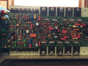
I have found some schematics for these that appear to be close but the problem is on mine. there is quite a few trimmer pots and test points. Without the service manual, you don't know what values you should see at the test points. As I remember while poking around the failed board that I found nothing actually failed. I suspect it has drifted out of spec and that's why it's tripping the fault circuit and shutting down. I know which amp module is causing the problem. If I disconnect it. the amp will stay powered up and four channels working. I really need the service manual.
Link in post #12 has no schematics. A lot of useless information like how to replace the power transformer and how to replace the heatsink. Schematics are on the back cover which were not reproduced. Toshiba 2SC3281 and 2SA1302 output transistors, which must be where On Semi
came up with their MJ products.
came up with their MJ products.
Last edited:
- Home
- Amplifiers
- Solid State
- Anyone have luck repairing a Proceed Amp5?