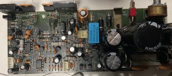
I was given a subwoofer that had an issue that the google reported could be fixed by replacing every small electrolytic capacitor.
I started pulling each cap and testing them with DATS V3 (and a DMM to make sure) and sure enough, each of the small 25-100uF caps appeared bad, typically less than 1uF and very high ESR compared to a new one. The larger PSU caps tested fine.
question 1: what might cause something like this to happen? All caps are 105C rated, FWIW.
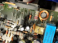
question 2: for one capacitor, the silkscreen shows a polarized capacitor schematic symbol but with the plus symbol on the wrong side: + —)|—
The cap in that position was oriented per the + symbol, not the schematic symbol. With this orientation, the negative lead is tied to the emitters of both of the 2SC5200 transistors. Does this look like the correct orientation?
I googled some 2SC5200 schematics but haven't come across one that has a polarized capacitor tied to the emitter.
Thanks.
I started pulling each cap and testing them with DATS V3 (and a DMM to make sure) and sure enough, each of the small 25-100uF caps appeared bad, typically less than 1uF and very high ESR compared to a new one. The larger PSU caps tested fine.
question 1: what might cause something like this to happen? All caps are 105C rated, FWIW.
question 2: for one capacitor, the silkscreen shows a polarized capacitor schematic symbol but with the plus symbol on the wrong side: + —)|—
The cap in that position was oriented per the + symbol, not the schematic symbol. With this orientation, the negative lead is tied to the emitters of both of the 2SC5200 transistors. Does this look like the correct orientation?
I googled some 2SC5200 schematics but haven't come across one that has a polarized capacitor tied to the emitter.
Thanks.
I don't know specifics of your question, but I have have identified bad caps in amps by pointing a hair dryer on it.
Sometimes bad caps that are warm and toasty actually "work", at least for a little while...
Laugh all ya want, works fer me!! 😀
Sometimes bad caps that are warm and toasty actually "work", at least for a little while...
Laugh all ya want, works fer me!! 😀
Important to know is WHEN these products were manufactured.
Bad electrolytics were frequent around the early/mid 2000's due to a faulty chemical composition.
As for mis-marking, it could be a manufacturing defect.
In operation, at idle, it would be wise to check voltage readings on said capacitor, and if reversed, correct the polarity.
Bad electrolytics were frequent around the early/mid 2000's due to a faulty chemical composition.
As for mis-marking, it could be a manufacturing defect.
In operation, at idle, it would be wise to check voltage readings on said capacitor, and if reversed, correct the polarity.
I can't find much info but I did find a review from '99. I don't see any decipherable date codes anywhere.
for one capacitor, the silkscreen shows a polarized capacitor schematic symbol but with the plus symbol on the wrong side: + —)|—
The cap in that position was oriented per the + symbol, not the schematic symbol. With this orientation, the negative lead is tied to the emitters of both of the 2SC5200 transistors. Does this look like the correct orientation?
To be sure, with the old capacitor in place apply power and measure the voltage polarity impressed on it.
I just powered it up with the old cap in place, oriented as I found it, and I get +50VDC.
So would that indicate the cap is oriented correctly?
I was surprised to see 50VDC as that is the voltage rating of that cap.
Most of the replacement caps I ordered are higher voltage than their original except for three. One is an NP that I had assumed was polarized. That was replaced with a part I had on hand with the same rating. The other two are 100uF 50V parts that I must have mistakenly ordered. However, I only see 15V across these so it appears I should be fine.
Last edited:
Yes, the positive terminal on the part should align with the measured voltage.
Not unusual to see poorly derated designs, I've seen 16V tantalums run at 15V,
which ended up bursting into flames and completely destroying the board.
Better to use at least a 75V capacitor if it has 50V on it.
Not unusual to see poorly derated designs, I've seen 16V tantalums run at 15V,
which ended up bursting into flames and completely destroying the board.
Better to use at least a 75V capacitor if it has 50V on it.
Last edited:
Sometimes I found similar failures. Obviously the small coupling caps with diameters like 5mm dry out much faster than the bigger ones.
I only have 63V at the moment. I'm feel okay taking that risk for the time being.
Thanks for the help!
Thanks for the help!
Technically, a 50V rating is adequate for 50V use, but the lifetime will be limited compared to derating.
Also there would be no margin for error to accommodate line voltage variation, transformer regulation, etc.
Also there would be no margin for error to accommodate line voltage variation, transformer regulation, etc.
when did the google actually troubleshoot your amplifier?the google reported could be fixed by
which is? .......had an issue
Dunno, never saw a schematic.With this orientation, the negative lead is tied to the emitters of both of the 2SC5200 transistors. Does this look like the correct orientation?
Besides: your question implies that 2SC5200 emitters are joined by a wire or trace, is that so?
Don´t they have individual ballast/emitter resistors?
Try to find your own.I googled some 2SC5200 schematics but haven't come across one that has a polarized capacitor tied to the emitter.
We don´t even know your subwoofer brand and model, have not seen board pictures.
The guy who gave it to me said he googled the issue (don't remember if he described it to me or not) and the solution was replacing all small caps on the board.
I googled it and found the same recommendation. I started removing and testing caps and found they all were way out of spec.
I'm not deeply invested in this sub but thought it would be fun if I could fix a free sub with $10 worth of parts. I'm not experienced enough to properly troubleshoot the issue.
The subwoofer is an Atlantic Technology 172 PBM
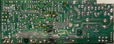
The capacitor whose polarity I was questioning is C25. I moved it to the bottom of the PCB to more easily test its polarity. This determined that the + symbol was correct and the capacitor symbol was backwards. The original cap was installed correctly but had failed.
info: ATLANTIC TECHNOLOGY 172 PBM INSTRUCTION MANUAL Pdf Download | ManualsLib
issue: Atlantic Technology PBM 172 Sub Standby Crackling | Audiokarma Home Audio Stereo Discussion Forums
I googled it and found the same recommendation. I started removing and testing caps and found they all were way out of spec.
I'm not deeply invested in this sub but thought it would be fun if I could fix a free sub with $10 worth of parts. I'm not experienced enough to properly troubleshoot the issue.
The subwoofer is an Atlantic Technology 172 PBM
The capacitor whose polarity I was questioning is C25. I moved it to the bottom of the PCB to more easily test its polarity. This determined that the + symbol was correct and the capacitor symbol was backwards. The original cap was installed correctly but had failed.
info: ATLANTIC TECHNOLOGY 172 PBM INSTRUCTION MANUAL Pdf Download | ManualsLib
issue: Atlantic Technology PBM 172 Sub Standby Crackling | Audiokarma Home Audio Stereo Discussion Forums
Attachments
- Home
- Amplifiers
- Solid State
- replacing failed caps