Got a RF P8002 in for repair. I opened up and cleaned and requested a schematic from RF this afternoon. PC-4708-B.
After disassembly and cleaning, I noticed R2071 (5 ohm) was popped from its position, where it had some charring on the pcb. This was cleaned and replaced with new. I checked the drivers in circuit and they checked ok. there were no shorts on any of the PS FETs, output FETs.
Amplifier was powered up: (gnd and remote) checked gate drive waveforms and they were good. Applied power with B+, amplifier is trying to start. It draws excessive current, shuts down and immediately restarts and the process repeats cycling until remote is removed.
Lifted D2001, D2002 one at a time and powered up, amplifier repeated cycling. Output FETs for channel 2*** are getting warm.
None of the protection lights are being lit.
I shorted one of the thermistors, and the amp went into thermal protection, where it stopped cycling.
Anyone ever had similar issues with these before?
Attachments
Yes I also lifted those, removing the protection circuitry. The amp does the same thing.
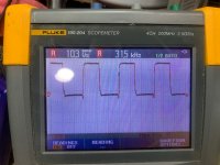
I’m working off another schematic until tomorrow. I jumpered D5, from looking at the sawtooth on pin 5 of the 494 it seems to shut off and come back up with the cycling. With D5 jumpered the amplifier doesn’t cycle on and off but draws high current. I believe D5 is the inline diode supplying power to the 494.
I’m working off another schematic until tomorrow. I jumpered D5, from looking at the sawtooth on pin 5 of the 494 it seems to shut off and come back up with the cycling. With D5 jumpered the amplifier doesn’t cycle on and off but draws high current. I believe D5 is the inline diode supplying power to the 494.
D5 supplies 12v to the 494 until the power supply starts operating. Then the supply is through D6.
Power up through a limiter. Do you have 4 FETs heating in the channel, all N-channel or all P-channel with none of the others heating?
Have you tried setting the bias fully CCW?
Power up through a limiter. Do you have 4 FETs heating in the channel, all N-channel or all P-channel with none of the others heating?
Have you tried setting the bias fully CCW?
Yes I got a inline limiter,
This version of the amplifier has 3 pairs of FETs per rail, 36P15 and 28N15, I cant tell if its just two out of the three are heating as three per rail are on one mesha and I didn't allow it remain powered on long enough to notice.
Initially I did set the bias CCW, but all attempts thus far didn't result in any changes.
OK. The diagram says not used for one FET. IT has 3 FETs per rail per channel.
Connect a multimeter across one of the 0.1 ohm source resistors and apply power. With the bias fully CCW, all should read 0.000v DC while the amp is drawing current. Check all 0.1 ohm resistors in the bad channel.
Which ones read above 0.000v DC?
Connect a multimeter across one of the 0.1 ohm source resistors and apply power. With the bias fully CCW, all should read 0.000v DC while the amp is drawing current. Check all 0.1 ohm resistors in the bad channel.
Which ones read above 0.000v DC?
I rechecked all components (R-ch) I found an open bias transistor TRK2000, and one open driverQ2012. I replaced all with new components, powered up and it turned on without cycling. passed clean audio. Onto final checks and assembly.....
thanks again for the help, much appreciated.
thanks again for the help, much appreciated.
Last edited:
- Home
- General Interest
- Car Audio
- Rockford Fosgate P8002 cycling on/off