Running a single 6SL7 tube with a 200VAC for the high voltage supply, rated for 40mA. I have a bridge rectifier, 100u reservoir cap, and three stages of RC filters (470R + 100u). I've had a couple transformers fail with this setup. I'm assuming an internal open circuit due to thermal stress. There is no AC on the secondary. Is my reservoir cap too big? Should I put a thermistor in series with the reservoir, or perhaps a low value resistor?
Last edited:
What transformer are you using? Some have internal fuses. Which winding failed open?
Edcor XPWR083A. 200VAC secondary failed open.
Three so far.How many failures have you had? Everything sounds reasonable.
How about installing a fuze ( should be on the AC side of the secondary)Running a single 6SL7 tube with a 200VAC for the high voltage supply, rated for 40mA. I have a bridge rectifier, 100u reservoir cap, and three stages of RC filters (470R + 100u). I've had a couple transformers fail with this setup. I'm assuming an internal open circuit due to thermal stress. There is no AC on the secondary. Is my reservoir cap too big? Should I put a thermistor in series with the reservoir, or perhaps a low value resistor?
Certainly if there is not one already, there should be a primary fuse (around 0.25A to 0.5A rating) regardless.
Possibly the input capacitor is too large. A series resistor of perhaps 1k 3W after the rectifier may help also.
Possibly the input capacitor is too large. A series resistor of perhaps 1k 3W after the rectifier may help also.
Last edited:
Edcor XPWR083A. 200VAC secondary failed open.
Three so far.
That's three strikes. Maybe try something bigger. I doubt you'll kill this: AS-1T200 - 100VA 200V Transformer - AnTek Products Corp
jeff
Probably is poorly made with very thin secondary wire ... 😀 and the charging of the capacitor at startup kills it , you could do some ohmic measurements if you still have a good one .
Probably is poorly made with very thin secondary wire ... 😀 and the charging of the capacitor at startup kills it , you could do some ohmic measurements if you still have a good one .
Probably. I've used this transformer for other projects and it's been pretty convenient. But I think they've been hastily made recently.
That's like 300-400mA surge at startup.I have a bridge rectifier, 100u reservoir cap, and three stages of RC filters (470R + 100u).
Changing all the caps from 100u to 10u decreases the surge by about 3x, while still providing decent filtering (~10mV ripple, so about -90dB with respect to 290V or so DC).
200 VAC, 40 mA -> 8 VA. So it seems unlikely that the transformer fries due to overload during steady state operation. Though, if you draw 40 mA DC from the power supply, you will be overloading the transformer. Typically you get about IRMS = 1.6*IDC, so your transformer should be rated for 64 mA RMS for a 40 mA DC current. The multiplier is due to the rather gnarly charging pulses drawn by a capacitor input power supply. Some transformer manufacturers specify the max. DC current assuming a capacitor input power supply. Some specify the max RMS current from the secondary winding. It may be worthwhile to toss Edcor an email to ask how they spec their transformers.
Plus the inrush of the transformer itself and of the first cap. I wrote quite a bit on that in the context of solid state power amps when I designed my Intelligent Soft Start. A soft start on the primary of the transformer would limit the current on the secondary as well.
You could add an NTC on the secondary. Then short it out with a time-delay relay once the supply has charged in true tube style.
The inrush current can reach hundreds of ampere in some cases. You can see my measurements and read my thoughts on soft start design here: The Ultimate Guide to Soft Start Design – Neurochrome
Tom
That's like 300-400mA surge at startup.
Plus the inrush of the transformer itself and of the first cap. I wrote quite a bit on that in the context of solid state power amps when I designed my Intelligent Soft Start. A soft start on the primary of the transformer would limit the current on the secondary as well.
You could add an NTC on the secondary. Then short it out with a time-delay relay once the supply has charged in true tube style.
The inrush current can reach hundreds of ampere in some cases. You can see my measurements and read my thoughts on soft start design here: The Ultimate Guide to Soft Start Design – Neurochrome
Tom
Last edited:
Its hard to advise without seeing the circuit.
1/ Fuse secondary.
2/ Could be 100uF is shorted or too low a voltage.
3/ Rectifier fault ? are they correct PIV voltage, at least 600 volts but better 1000 volts.
1/ Fuse secondary.
2/ Could be 100uF is shorted or too low a voltage.
3/ Rectifier fault ? are they correct PIV voltage, at least 600 volts but better 1000 volts.
I agree, we need to see a schematic.
A 40mA B+ winding is burning out, when the only load is a single 6SL7?
How is that?
I think if I saw a 6SL7 that had 40mA of plate current, that would take a very large amount of grid current to get that much plate current.
And if that happened, I would expect the plate to be glowing red, and perhaps the grid would be glowing too.
Even if we divide 40mA by 1.6, to keep it safe for a Capacitor input filter, that is 25mA. A 6SL7 will either glow with 25mA, or at least destroy itself over time.
Look for some kind of wiring error.
6SL7 Socket pinout connections.
Bridge rectifier connections.
Electrolytic polarity reversed.
Etc.
Last edited:
If this were mine I'd check for SC's by measuring resistance across the 100u cap before powering up and checking to see that there are no mistakes.
Use a lamp limiter to power it up after inserting fuses on the priamry and secondary whilst monitoring AC current as well as HT. I'd bung a scope on the AC out of the tfmr too whilst I was at it, hand on the off SW so you can kill power if anything's amiss.
That said something doesn't sound right, tfmr's are pretty hard to kill, they usually buzz if they're not happy or get hot, not fail OC.
Andy.
You live in a 120v mains country.
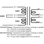
Did you check that both 120v primary windings are actually connected in parallel.
If not, 2x overloaded.
All transformer pins well soldered and Pins 1 & 2 connected together as well as Pins 5 & 6 connected together, check PCB traces whether this is the case and no cracks or so ...
Measure secondary AC voltages and DC voltages when amp is on. If a permanent overload condition exists I would expect to see lower than nominal values.
How hot does the transformer get after an hour or so ? This transformer could have a thermal fuse built deep into the primary winding which is not repairable and will fall open somewhere between 100 and 130 deg Celsius internal winding temperature.
Check the faulty transformers which you replaced earlier with your ohm meter whether and which of the primary or secondary windings has failed.
Attachments
Last edited:
There has got to be something going on that somebody not telling us. The secondary just won’t fail open unless it is also getting HOT. Even the high peak currents associated with cap charging would still cause heat due to the high RMS value. If it doesn’t cause heat it won’t hurt the winding unless you’re up in the multiple-ampere range. And I doubt even a shorted secondary would develop enough amperage to kill it in less than 10 seconds. Turn on DC surges or excessive magnetostriction usually kill the primary because that’s which winding sees those stresses. One initial start up pulse won’t do it - it needs to be repetitive and sustained to do any damage. That usually makes telltale noises - and usually heat too.
Now if there were manufacturing defects you might be able to induce failure. Still probably won’t happen without heating also occurring.
Now if there were manufacturing defects you might be able to induce failure. Still probably won’t happen without heating also occurring.
I reckon it's a cumulative error. Seems crazy to destroy three transformers. I would say a short circuit diode in the bridge rectifier started the tail of woe. This caused the cap to get half wave rectified DC with the full AC on top breaking down the caps very thin layer of aluminium oxide causing it to look like a short. Dead bridge rectifier and nailed caps. Replace all the electrolytics and the rectifier. Probably a reason the rectifier died as has been said. Be sure the replacement is up to the task. 1000V PiV is the way.
- Home
- Amplifiers
- Tubes / Valves
- Tube pre kills HV transformers