Hi all, been reading for a while but first post. I'm an audioholic, not phile! I recently got my first valve stereo preamp, however it developed a fault and I'm struggling to find a schematic for a similar preamp. Im no expert so try not to blind me with science but I do have a reasonable understanding of electronics. I think it is a push pull, it has a single 12AU7 running into 2 12AX7s 1 per channel, it also has what I think is a transistor ( 4 legs) that seems to provide some sort of balance, it's connected to pins 4&5 on all tubes.
I'm trying to draw a schematic but I keep getting lost! It has a tube rectifier and a second transformer, but this isn't output, I assume its a 12vac supply.
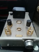
Another oddity, it has 2 volume controls, an alps 50k inside which I assume is used like a gain preset and an r/c alps 100k.
Any help greatly appreciated, I've got to the point now I'd prob find rebuilding it easier than fault finding hence wanting a schematic. The caps are all wima and it uses flee bay relay switching and remote volume. Cheers Simon
I'm trying to draw a schematic but I keep getting lost! It has a tube rectifier and a second transformer, but this isn't output, I assume its a 12vac supply.
Another oddity, it has 2 volume controls, an alps 50k inside which I assume is used like a gain preset and an r/c alps 100k.
Any help greatly appreciated, I've got to the point now I'd prob find rebuilding it easier than fault finding hence wanting a schematic. The caps are all wima and it uses flee bay relay switching and remote volume. Cheers Simon
A lot of guess work at this point.
Let me take a shot: the 12AX7 per channel for phono, and the 12AU7 shared, one half per channel.
The chip going to pins 4&5 is providing dc to the heaters.
Let me take a shot: the 12AX7 per channel for phono, and the 12AU7 shared, one half per channel.
The chip going to pins 4&5 is providing dc to the heaters.
ECC8* Valves or 12A*7 Tubes are read from underneath, clockwise pins1 to 9;
Anode 1, Grid 1, Cathode 1, Heater, Heater, Anode2, Grid 2, Cathode 2, Heater Centre tap.
Probably has 12volts between pins 4 & 5 for the heaters.
Hope that helps but as I can't physically see it, that is as far as I can go.
Anode 1, Grid 1, Cathode 1, Heater, Heater, Anode2, Grid 2, Cathode 2, Heater Centre tap.
Probably has 12volts between pins 4 & 5 for the heaters.
Hope that helps but as I can't physically see it, that is as far as I can go.
Thanks all so far, I know the pinouts, just can't find a schematic that uses a shared 12au7 and 2 ax7s, yes the chip is linked to heaters.
It's confusing me because A, it has 2 sets of inputs with 2 volume controls and
B, the output signal path comes from pins 8 on the ax7s, cathode. I expected this to be from the anode?
Really impressed with the speed and level of help, thanks
It's confusing me because A, it has 2 sets of inputs with 2 volume controls and
B, the output signal path comes from pins 8 on the ax7s, cathode. I expected this to be from the anode?
Really impressed with the speed and level of help, thanks
Attachments
The thing with 4 pins is a bridge rectifier. Pins 4/5 are the ends of the heaters in both 12AU7s and 12AX7s.
A 12AX7 in each channel, along with a section of the 12AU7, is a common configuration for a phono section. Two stages of voltage amplification and a cathode follower (buffer) to drive the downstream load. However, the LEDs indicating which source is selected show only line level. That looks like very bad engineering to me, with enormous amounts of gain that's not needed.
Your thinking about the internal level control is probably correct. I'm guessing it's used to adjust sensitivity for "line" level sources, like CDPs.
What is the rectifier type? The socket appears to be Octal and that suggests a 5Y3 "equivalent".
Please provide a photo of the insides.
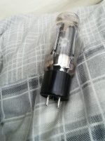
Hi all, unfortunately for me the tubes screenprinting is gone, I think the rectifier is a 5u4, it's 4 pin.
All I want really is a schematic I can follow to rebuild it using the parts I have already.
The gain didn't seem too high, I'm driving 2x denon 100wpc amps ( it has 2x stereo out)
With both vols on preamp maxed I didn't get any distortion pushing to amps to around 60-70 Watts.
I'm unsure which internals you wanted pictures of.
Cheers
Attachments
A photo has been provided. Thank you!
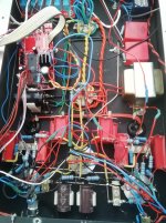
What at 1st glance looks like a transformer mounted on the inside is (IMO) likely a B+ PSU filter choke.
That the signal circuitry is wired point to point (P2P) and not on a circuit board is a blessing. Silly, "propaganda", engineering is easily replaced with circuitry that comports with good practices.
Don't for 1 second trust the branding of parts. 🙁 Chinese counterfeits are all too likely.
The knob on top of the chassis reveals the likely true purpose of the 50 Kohm non-RC control. I strongly suspect a MN taper balance control. RC fiddling with listening level is fairly frequent, but channel to channel balance adjustments are, likely, infrequent.
What at 1st glance looks like a transformer mounted on the inside is (IMO) likely a B+ PSU filter choke.
That the signal circuitry is wired point to point (P2P) and not on a circuit board is a blessing.
Silly, "propaganda", engineering is easily replaced with circuitry that comports with good practices.Don't for 1 second trust the branding of parts. 🙁 Chinese counterfeits are all too likely.
The knob on top of the chassis reveals the likely true purpose of the 50 Kohm non-RC control. I strongly suspect a MN taper balance control. RC fiddling with listening level is fairly frequent, but channel to channel balance adjustments are, likely, infrequent.
Can anyone point me to a schematic I could follow using what parts I've got to make a half decent preamp? By half decent I know it's only as good as the components, but as this design has been called horrible, perhaps a better one.. Cheers
Be careful inserting your rectifier valve. You have the locating spigot snapped off...
Look very carefully at the base and identify where the 'bump' that aligns the valve properly is. That must line up with the indent / locator of the valve holder. Or nothing will work.
Look very carefully at the base and identify where the 'bump' that aligns the valve properly is. That must line up with the indent / locator of the valve holder. Or nothing will work.
All I want really is a schematic I can follow to rebuild it using the parts I have already.
The gain didn't seem too high, I'm driving 2x denon 100wpc amps ( it has 2x stereo out)
With both vols on preamp maxed I didn't get any distortion pushing to amps to around 60-70 Watts.
Lots of open loop gain and lots of NFB to limit the closed loop net gain. 😡 "Padding" of the volume control circuitry to "dump" excess gain could also be present. That damages S/N performance.
Most modern power amplifiers can be driven into clipping by the 2 VRMS O/P of a "standard" CDP. Therefore, line stage voltage gain is not needed and, in fact, its presence is harmful. All that's needed in a control center for "modern" signal sources is selection among the said sources and the ability to drive the downstream load. One bottle, a 12BH7, wired as 2X cathode followers does the job. The 12BH7 is pin compatible with the 12AU7.
You keep the microprocessor governed source selection and listening level control intact. Many of the B+ PSU parts can probably be retained. If, in fact, the vacuum rectifier is a 5U4 "equivalent", buy an ElectroHarmonix (EH) 5U4GB and don't look back. Chinese and Russian ST envelope ("coke bottle") 5U4 "equivalents" are total garbage.
If a turntable and analog records are owned, a quite decent phono preamp can be made around the 12AX7s. No phono makes the 12AX7s superfluous.
Thanks and umm a lot of that I'll be googling! I think you meant I don't need the preamp stage without phono, while I don't necessarily need the gain it does provide me with remote volume control for the amps and when it worked properly the sound was considerably warmer. As the preamp has the cutouts if all tubes are not required they could remain as dummies with the heaters, but I'm still without a schematic I can use. Any suggestions, remember I'm novice at this! Cheers
Hi it just makes a fart noise now, but the way it's built its very hard to access a lot of it for testing, it's double skinned and all retaining nuts are between the skins. This means all tubes, transformer etc have to be removed just to get into it.
If I'm going that far, I'd prefer wire it to a schematic I have access to, I currently don't have one for it. Cheers
If I'm going that far, I'd prefer wire it to a schematic I have access to, I currently don't have one for it. Cheers
@simongill
What I have in mind is for you to retain the existing source selection and volume control stuff, without change. Simple cathode followers will drive the O/P jacks.
Cathode followers have a voltage gain (α) of slightly less than 1. IOW, a small voltage insertion loss is present. By paying that price, you acquire current gain and a low O/P impedance. Those "rewards" are exactly what's needed to drive your SS power amplifiers. 😀
Last edited:
@simongill
What I have in mind is for you to retain the existing source selection and volume control stuff, without change. Simple cathode followers will drive the O/P jacks.
Cathode followers have a voltage gain (α) of slightly less than 1. IOW, a small voltage insertion loss is present. By paying that price, you acquire current gain and a low O/P impedance. Those "rewards" are exactly what's needed to drive your SS power amplifiers. 😀
Thanks Eli, I like the look and sound of this. Am I looking for a circuit that is only the cathode follower or one that utilises both tubes like a preamp stage with a cathode follower? Cheers Simon
- Home
- Amplifiers
- Tubes / Valves
- Newb needs help!