Hey People,
I just ordered some PCB's for the open source LM3886. I'm planning to build a 2.1 stereo Set, and want to use three LM3886 for each 2.5-Way Speaker (2x 5 1/2" Mid/Bass + 1x 1" soft Dome Tweeter).
The Speakers will have two Enclosures on the Back, the 1st will be 130mm high, 250mm deep and 164mm wide. There I will put 2 Drawer-Rails of 246mm on the 22mm MDF Ground-Plate and upon these a matching 3mm Aluminium-Plate.
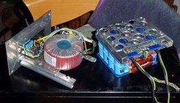
This will be the Enclosure for the 300VA Toroid (2x18V/ 2x 8,33A).
The upper Enclosure will be measured (HxWxD) 400x164x250mm. Same Construction as below, 2 Drawer-Rails on MDF, 3mm Aluminium Plate on Top of the Drawer-Rails.
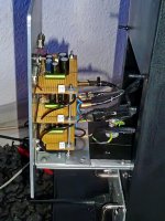
The three LM3886 will be stacked and mounted on the 5mm Aluminium Backplate which also closes the upper Chamber.
I did this before with LM1875 and I am really satisfied with the result for it was a more or less "0 Budget" Project, and therefore it's Ok.
I'm planning the new Speakers as just a improved Version of the first Attempt, just with slightly more Budget and without all the Mistakes I did at the first Try. The Dimensions of the Box and the Enclosures will be pretty much the same as they were at Mk.I.
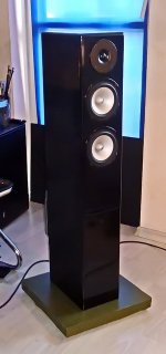
Imagine the Box like the one on the Pics, just a little prettier 😉.
Ok, here is my Question: I've got to supply 3 Amps with 1 Toroid. Not really a problem, I did this before with the three LM1875. Anyway, I want to get the best Results, and I am just a Mechanic. I'm learning by doing 😉.
So how would You do this?
I am thinking of one "Main" PSU PCB with 8x MUR860, 2k2/2W Bleeders, 1R/10W, about 60000uF (3x 15000uF + 4x 4700uF) Capacity per Rail, 100nF, 0.47R/1.5nF Snubber. This is the unregulated "Snubberized PSU MkIV SE Rev.3" by Carlos Filipe. So I would put the rectifying Part and most of the Capacity in the lower Enclosure. Now I got ca. +/-28V which I like to lead to the upper Champer and distribute it to the Amps.
At this Point I also want to set my Starground. I thought about some extra uF (Mid/Bass 4x(8x) good Quality 1500UF/50V, Tweeter 4x(8x) 680uF/50V) on small (60x80mm) PCB's to put right behind the Amplifier PCB's.
Is there something I'm not aware of? Would this work? Are there good Quality 1 in 3 out Wire Distributors to buy online? I'm always thinking of a Connection which I'm closing by pushing the "Amp-Sled" on it's Drawer-Rails in. Maybe You know a simple Solution I am not aware of.
If I give each LM3886 such an extra Capacity-PCB, would you put Bleeders and a Snubber RC on it?
What should I use as, not so expensive, Signal Cable? I've got 3 Signals for each Side. I'm thinking about Cat.7 Network-Cable. Could this be worth a try?
Best Regards
Jochen
I just ordered some PCB's for the open source LM3886. I'm planning to build a 2.1 stereo Set, and want to use three LM3886 for each 2.5-Way Speaker (2x 5 1/2" Mid/Bass + 1x 1" soft Dome Tweeter).
The Speakers will have two Enclosures on the Back, the 1st will be 130mm high, 250mm deep and 164mm wide. There I will put 2 Drawer-Rails of 246mm on the 22mm MDF Ground-Plate and upon these a matching 3mm Aluminium-Plate.
This will be the Enclosure for the 300VA Toroid (2x18V/ 2x 8,33A).
The upper Enclosure will be measured (HxWxD) 400x164x250mm. Same Construction as below, 2 Drawer-Rails on MDF, 3mm Aluminium Plate on Top of the Drawer-Rails.
The three LM3886 will be stacked and mounted on the 5mm Aluminium Backplate which also closes the upper Chamber.
I did this before with LM1875 and I am really satisfied with the result for it was a more or less "0 Budget" Project, and therefore it's Ok.
I'm planning the new Speakers as just a improved Version of the first Attempt, just with slightly more Budget and without all the Mistakes I did at the first Try. The Dimensions of the Box and the Enclosures will be pretty much the same as they were at Mk.I.
Imagine the Box like the one on the Pics, just a little prettier 😉.
Ok, here is my Question: I've got to supply 3 Amps with 1 Toroid. Not really a problem, I did this before with the three LM1875. Anyway, I want to get the best Results, and I am just a Mechanic. I'm learning by doing 😉.
So how would You do this?
I am thinking of one "Main" PSU PCB with 8x MUR860, 2k2/2W Bleeders, 1R/10W, about 60000uF (3x 15000uF + 4x 4700uF) Capacity per Rail, 100nF, 0.47R/1.5nF Snubber. This is the unregulated "Snubberized PSU MkIV SE Rev.3" by Carlos Filipe. So I would put the rectifying Part and most of the Capacity in the lower Enclosure. Now I got ca. +/-28V which I like to lead to the upper Champer and distribute it to the Amps.
At this Point I also want to set my Starground. I thought about some extra uF (Mid/Bass 4x(8x) good Quality 1500UF/50V, Tweeter 4x(8x) 680uF/50V) on small (60x80mm) PCB's to put right behind the Amplifier PCB's.
Is there something I'm not aware of? Would this work? Are there good Quality 1 in 3 out Wire Distributors to buy online? I'm always thinking of a Connection which I'm closing by pushing the "Amp-Sled" on it's Drawer-Rails in. Maybe You know a simple Solution I am not aware of.
If I give each LM3886 such an extra Capacity-PCB, would you put Bleeders and a Snubber RC on it?
What should I use as, not so expensive, Signal Cable? I've got 3 Signals for each Side. I'm thinking about Cat.7 Network-Cable. Could this be worth a try?
Best Regards
Jochen
Attachments

Connectors wise, no idea. I would put angled spade connectors on the boards and terminate the incoming PSU wires with insulated fastons.
For the PSU, I personally would think that about 22 000uF per rail is plenty enough. More will be a very marginal improvement. I wouldn't have a starground away from the main PSU pcb. I'd rather have each pcb with its own wires triplet going back to the main PSU low impedance output. With a 18Vac transformer, you can put 4 1000uF/35V caps per pcb, which isn't too bad on its own.
Nice concept and execution on that speaker btw. 🙂
Many thanks for the tipps. You are right with the Starground. I'll put it on the main Rectifier/PSU PCB. You are also right with the amount of Capacitance, but I got still a whole Bunch of really fine LCR 4700uF/35V. I won 100 of them for 10€ at the bay and they are still over their nominal Capacitance. The Pack on the Picture did a really good Job with the three LM1875.
Attachments
"I just ordered some PCB's for the open source LM3886"
Are these custom boards or off the shelf? Would you please post where you bought them?
Thank you.
Are these custom boards or off the shelf? Would you please post where you bought them?
Thank you.
"I just ordered some PCB's for the open source LM3886"
Are these custom boards or off the shelf? Would you please post where you bought them?
Thank you.
here you find all what you need:
An open source layout for LM3886?
chris
Thanks @ chermann, thats where I got the Gerber-Files from.
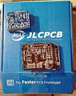
I ordered 10 PCB's for the LM3886 and 10 for the LM1875 about 10 Days ago, and Today I got a parcel from China. They sent it via Airmail, wow! 😀
20 PCB's custom made and sent from China to Germany in 10 Days for just 13,38€. This is a DIY'ers Dream 😉.
I ordered 10 PCB's for the LM3886 and 10 for the LM1875 about 10 Days ago, and Today I got a parcel from China. They sent it via Airmail, wow! 😀
20 PCB's custom made and sent from China to Germany in 10 Days for just 13,38€. This is a DIY'ers Dream 😉.
Attachments
- Home
- Amplifiers
- Chip Amps
- 2.5-way active Speaker w/ 3x open source LM3886 > PSU?