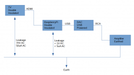
In my setup there is a double insulated device without earth connection (TV, Class II) interconnected to an earthed device (amplifier, Class I). See attached image for description. The shield of the HDMI cable has a measurable potential difference to earth, and through the cables of the chained devices a current flow to earth. This current is passing through the RCA cables to the amplifier and 1)slightly but annoyingly enough to my ears degrades the audible result 2)makes some protective relays in the DAC switching on-off whenever I connect the TV.

I'm looking for a possible solution to this issue. I cannot change to balanced connections and I cannot throw the TV out of the window for the time being. I'm thinking about building a earthed linear power supply for the Raspberry Pi (device between the TV and the amplifier) where most of the leakage current will find its way to the earth before reaching the audio cables. Is it reasonable?
Regards!
Attachments
Are those measurements to the Protective Earth/Safety Ground of the AC mains circuit powering the amplifier?
the 70 Volt AC measurement is probably what electricians call phantom voltage. That's when a unconnected wire is measured with a modern high impedance DMM.
the 70 Volt AC measurement is probably what electricians call phantom voltage. That's when a unconnected wire is measured with a modern high impedance DMM.
Yes, this is how they call it, I think. The measurements are from the exposed metal parts of each device in reference to the PE/SG of the AC mains circuit (230V/50Hz), while being powered on and not interconnected to any other devices, using one or two reliable DMM, for a sufficient amount of time for the reading to stabilize. Tried both orientations (polarities) of the european schuko socket on the wall and the lowest measurement is chosen.Are those measurements to the Protective Earth/Safety Ground of the AC mains circuit powering the amplifier?
the 70 Volt AC measurement is probably what electricians call phantom voltage. That's when a unconnected wire is measured with a modern high impedance DMM.
Last edited:
As opposed to "phantom powered microphones" or phantom powered antenna signal boosters (masthead amplifiers ) .
But yes that's why I still have my old AVO 8 (pre printed circuit model ). Found out about that very long time ago when testing open ended communications wiring in a university .
But yes that's why I still have my old AVO 8 (pre printed circuit model ). Found out about that very long time ago when testing open ended communications wiring in a university .
I use this HDTV converter https://www.newark.com/qfx/cv-103/digital-convertor-box-hdtv-tuner/dp/31AC3160?st=hdmi%20converter
to drive my audio amp and speakers. Has RCA jacks left right. Allows me to turn the horrid sound of the flat screen TV off. 2 cm x 15 cm speakers, what a laugh.
Newark usa is Farnell worldwide. You'll need to buy a 220 vac version from your European Farnell outlet.
I use a RG-45 splitter to connect the roof antenna to both TV & HDTV converter. This allows me to access low power TV stations in windy or rainy weather.
There are also hdmi splitters that provide line level RCA jacks out. However my only source is parts-express.com, that doesn't sell 220 versions of anything. Those are powered by a wall outlet transformer, which perhaps can be substituted for a 220 v version.
Last edited:
I use this HDTV converter ...
Thanks for the suggestion! My audio source is always the Raspberry Pi (a small computer) and the DAC. The TV serves the purpose of the display interface for the computer. No audio signal travels from the TV to the rest of the devices.
My main question is if it's ok to ground the computer to PE, in order to minimize the (phantom/stray) current leakage from the TV to the amplifier. Or any alternative idea;
Regards!
Phantom pickup is just that ---phantom m you can get it in many domestic appliances like fridges, its not "real voltage " and is usually related to your actual ring main wiring earth.
Its induced voltage so no current actually exists even one of those neon (or equivalent test pen probes) will light up when near a high voltage .
You are actually reading a magnetic flux due to high impedance's used to test.
Use an analog meter if you are that worried .
Why aren't any of you not worried about something much more important an earth loop test to measure a the impedance of the return earth in relation to the socket being used ?
Ignoring that can have "shocking consequences " if its a high reading.
Thanks for the input....
Its induced voltage so no current actually exists even one of those neon (or equivalent test pen probes) will light up when near a high voltage .
...
Use an analog meter if you are that worried .
...
Sure, I get this phantom voltage in all class II appliances, but as I mention on the first post, here there is an actual persistent current 50uA AC flowing between the TV and protective earth, that disturbs the clarity of the sound and also triggers some protective relay in the DAC.
How an analog meter will give a different measurement? I have one, but it is cheap, small and not sensitive enough for such low amperage.
Regards!
DVM with a fet input will show significant voltage on femtoamps. same with VTVM (vacuum tube voltmeters). Analog VOM have impedance of rating * full scale voltage, as 20000 ohms/volt * 20 volt scale or 400000 ohm impedance.
If your rasberry pi is receiving data over a network, or playing USB sticks, then you can't get rid of it. If you can access the chassis, I'd try connecting it to safety ground with a 470k resistor or similar. The DAC that is acting up is not grounded at all, or possibly grounded through the ring of the RCA jack to the amp RCA jack ring.
You might also get into the power amp and connect speaker return to chassis with 470k ohm. Unless the speaker is transformer isolated, in which case you need to get to the analog ground before that. My MMA-875t and MMA81502 amps both have transformer isolated speaker outputs, which are a plus IMHO when direct coupled transistor outputs damage speakers frequently at end of life. Vacuum tube power amps also have transformer isolated possibilty on speaker outputs. What the power amp does with the ring of the RCA input jack is important data. Pro PA amps run both center and outside of RCA jack to inputs of op amps, to break up ground loops.
The source of leakage current from the television is not obvious, and opening one up it is not obvious where to attach a 470 k resistor to safety ground to get rid of it. Some pin of the HDMI cable going into the rasberry pi would be a good place, but I don't have data on those cables or interfaces.
Last edited:
Seems to me the RaspberryPi can be hard-grounded. This will(?) divert the TV's RF-bypass current away from the audio path.
Thanks everyone for the replies.
Will try this and come back with the results.
Regards!
Seems to me the RaspberryPi can be hard-grounded. This will(?) divert the TV's RF-bypass current away from the audio path.
Will try this and come back with the results.
Regards!
The best place to interrupt ground-loop (common-mode) currents is at the signal interfaces between components. The most effective solution here is a signal isolation transformer. Such as:
CI-2RR | Jensen Transformers
There are other methods where ground-noise current may be interrupted, however, those require modifications to a component's mains safety-ground connection.
CI-2RR | Jensen Transformers
There are other methods where ground-noise current may be interrupted, however, those require modifications to a component's mains safety-ground connection.
Strictly speaking, you want both in a situation like this - galvanic isolation plus diverting the offending leakage currents to earth. Otherwise the transformer would see substantial common-mode voltage, potentially taxing its CMRR.
It wouldn't seem to matter much to me where exactly the earthing point should be, either the TV or the Pi should be fine. TVs usually have some antenna connectors that would lend themselves to this; alternatively if you have an Ethernet switch with built-in power supply and shielded network cabling that would be another option.
Galvanic isolation could be provided by either a line-level isolator for the audio or a USB isolator for the DAC. Both have their pros and cons.
The CT-2RR specs show some problems of high-impedance line-level transformers:
It is uncommon for line-ins not to have at least 100-200 pF worth of input capacitance, so you'd generally need a cable of length zero to minus 3 meters or even less.
You'd be way better off buying the bare transformers and integrating them into the amplifier (following any input capacitance), with insulated RCA jacks of course.
Guess why the trusty Behringer HD400 is a 600:600 ohm job. It's harder to drive and won't take as high levels, but at least you can use the thing with real cables as long as you watch their length.
USB isolators are fairly cheap and plentiful if USB 1.1 level data rates will do. If you need 2.0 speeds (read, 480 MBit/s) you can pretty much add a zero to the price tag. USB 3.0 (SuperSpeed) is actually easier to do than that as RX and TX lines are separated.
It wouldn't seem to matter much to me where exactly the earthing point should be, either the TV or the Pi should be fine. TVs usually have some antenna connectors that would lend themselves to this; alternatively if you have an Ethernet switch with built-in power supply and shielded network cabling that would be another option.
Galvanic isolation could be provided by either a line-level isolator for the audio or a USB isolator for the DAC. Both have their pros and cons.
The CT-2RR specs show some problems of high-impedance line-level transformers:
Code:
Output impedance, Zo 	1 kHz, test circuit 1 	  	4.65 kΩ
Allowable load capacitance 	 	0 	50 pF 	100 pF
(cable & input capacitance loading the ISO-MAX output)You'd be way better off buying the bare transformers and integrating them into the amplifier (following any input capacitance), with insulated RCA jacks of course.
Guess why the trusty Behringer HD400 is a 600:600 ohm job. It's harder to drive and won't take as high levels, but at least you can use the thing with real cables as long as you watch their length.
USB isolators are fairly cheap and plentiful if USB 1.1 level data rates will do. If you need 2.0 speeds (read, 480 MBit/s) you can pretty much add a zero to the price tag. USB 3.0 (SuperSpeed) is actually easier to do than that as RX and TX lines are separated.
I've read this is only an issue if you can hear hum, correct me if I'm wrong.there is an actual persistent current 50uA AC flowing between the TV and protective earth, that disturbs the clarity of the sound
The common (GND) of all signal wires from the TV to the amplifier input should have continuity. Check this first. The amplifier chassis, being a Class I device, should be connected to the PE, but the signal GND should not. Check also this.
Have you tried a Ground Loop Breaker (a 10R resistor between signal GND and protective earth PE, with a parallel high current antiparallel diode or bridge rectifier, inside the amplifier)? It should solve your problem.
Have you tried a Ground Loop Breaker (a 10R resistor between signal GND and protective earth PE, with a parallel high current antiparallel diode or bridge rectifier, inside the amplifier)? It should solve your problem.
- Home
- Amplifiers
- Power Supplies
- Grounded and ungrounded device in the audio chain