How should the miller capacitance of beam power tube like kt88 or kt150 be expected when they are strapped in triode arrangement?
januaryabc,
Great Question!
You are really thinking.
Here is my theory, right or wrong . . .
The screen g2 still shields the plate from g1 (even though now the plate and screen move together). Call that Cg1p.
That means the capacitance from g1 to plate is still the same as in pentode/beam power mode specs.
The capacitance of screen g2 to g1 is unchanged. Call that Cg1g2.
The mu (u), g1 to g2 of the tube is listed for most pentodes and most beam power tubes.
In triode mode, the effective rp of the plate plus screen in parallel is lower.
The gain of triode wired mode (with the new triode mode rp) . . .
(u = 1) x (RL/(RL+rp)) = Gain.
Gain x (Cg1g2 + the original low Cg1p) = Miller effect C.
Genalex Cg1 to a, g2 = 7.9pF (Triode mode); Cg1 to a = 1.2 pF (Tetrode mode); u= 8 Triode mode
https://frank.pocnet.net/sheets/086/k/KT88.pdf
It looks like the highest capacitance from g1 to g2 is the main factor in Triode mode.
A 300B with Cg1 to Plate = 15 pF, and u = 3.85 has about the same Miller Effect capacitance as a Triode wired KT88.
If someone knows more accurately, please give us the full story.
Thanks!
Last edited:
More theory:
g1 can not "see through g2" to the plate any differently, whether g2 voltage is fixed, or whether g2 and plate are tied together.
The ability of g1 "Seeing through g2"; and the area of g1, the area of the plate, and space from g1 to plate are the determinants of capacitance.
“Those who do not know history, are not aware that we are in Deja Vu.”
januaryabc, are you using that effective miller capacitance as part of estimating the RC roll-off of a driver stage's output?
If so then are you also adding in Cg* to everything but the screen and anode, to get a total Cg for RC calculation? And how are you managing with calculating the effective R of your driver?
If so then are you also adding in Cg* to everything but the screen and anode, to get a total Cg for RC calculation? And how are you managing with calculating the effective R of your driver?
trobbins,
Good points.
Cg1 to cathode
Cg1 to filament
Capacitance of wiring that is connected to g1 (wires to chassis, top end of Rg to chassis, coupling cap to chassis, etc.).
It all adds up.
Good points.
Cg1 to cathode
Cg1 to filament
Capacitance of wiring that is connected to g1 (wires to chassis, top end of Rg to chassis, coupling cap to chassis, etc.).
It all adds up.
januaryabc, are you using that effective miller capacitance as part of estimating the RC roll-off of a driver stage's output?
If so then are you also adding in Cg* to everything but the screen and anode, to get a total Cg for RC calculation? And how are you managing with calculating the effective R of your driver?
I know how to find the miller capacitance of triode but for KT150 the necessary information seems unavailable from the datasheet. So it's grateful if someone have experience on this tube in triode mode could provide some insight or estimation on the miller capacitance as a rule of thumb reference.
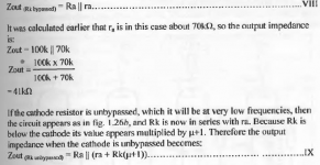
I calculate the output impedance by using the formula in the pic. The Rg of output stage will also be incorporated as parallel resistor and grid stopper as resistor in series after the output impedance is found. Is that a correct?
Besides, there are comments on "impedance bridging", which means the output impedance of previous stage should be much smaller than the input impedance of the next stage to avoid distortion. However it seems very little reference available discussing how to quantify the distortion/ effect. So I would be grateful if someone could share what they know on this point
Attachments
Last edited:
The resistances that are paralleled are your internal anode, external anode load, and next stage grid leak, and then any next stage grid stopper is added. The internal anode resistance may depend on the cathode arrangement, although some drivers that have a constant cathode voltage (such as a common cathode push-pull driver for when an earlier phase splitter stage is used) don't need inclusion of cathode resistance.
The RC roll-off calculation is based on fixed resistances and capacitances. If a particular part of the lumped resistance varies with signal voltage (such as internal anode resistance) then the the voltage transfer ratio varies during a cyclic swing of voltage, which is a distortion generating mechanism.
The RC roll-off calculation is based on fixed resistances and capacitances. If a particular part of the lumped resistance varies with signal voltage (such as internal anode resistance) then the the voltage transfer ratio varies during a cyclic swing of voltage, which is a distortion generating mechanism.
- Home
- Amplifiers
- Tubes / Valves
- Miller capacitance for beam power tube triode strapped