Hi all, seeking some guidance with my first (from scratch) tube amp build. Have decided to go with the original RH84 circuit for its simplicity and generally positive feedback.
Have a power and output transformers pulled from an old German (Loewe) console stereo. The original configuration of the amp was single ended, 2 x EF 86 driver tubes into 2 x EL84 outputs.
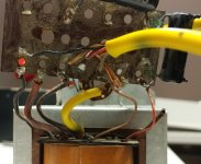
The power transformer doesn't have a center tap and measures at 310V with resistance is 100ohm. The opts appear to have multi-ohm speakers taps – have attached a pic of one of the opts.
I understand the impedance needed for the opt should be 5k, have been trying to calculate the impedance of the opt primary. Getting a very strange reading: when applying low voltage AC (2-6V) getting approximately 1.5x that on the secondary?
edit - I meant when applying the low AC on the secondary getting about 1.5x on the primary side
Will these be suitable for a RH84 (ver1) build? Assuming I can get the opt measured correctly.
Thanks.
Have a power and output transformers pulled from an old German (Loewe) console stereo. The original configuration of the amp was single ended, 2 x EF 86 driver tubes into 2 x EL84 outputs.
The power transformer doesn't have a center tap and measures at 310V with resistance is 100ohm. The opts appear to have multi-ohm speakers taps – have attached a pic of one of the opts.
I understand the impedance needed for the opt should be 5k, have been trying to calculate the impedance of the opt primary. Getting a very strange reading: when applying low voltage AC (2-6V) getting approximately 1.5x that on the secondary?
edit - I meant when applying the low AC on the secondary getting about 1.5x on the primary side
Will these be suitable for a RH84 (ver1) build? Assuming I can get the opt measured correctly.
Thanks.
Attachments
Remember, the impedance ratio of a transformer varies with the square of the turns ratio. Use a 1KHz. tone, when taking a measurement. Low quality console O/P "iron" might not handle the AC mains' frequency correctly.
No CT on the rectifier winding "forces" bridge rectification of B+. 4X UF4007s will get the job done. That 310 VRMS measured will "droop" under load.
An EF86 draws 200 mA. of heater current, while a 12AT7/ECC81 or 12AX7/ECC83 section draws 300 mA. of heater current. The power trafo might not be up to to the task at hand.
If possible, please provide the Löwe console schematic.
Hi Eli, I think the power transformer heater filament current draw should be OK. Instead of 2 EF86's, there is a single 12AT7 (for example), and that is just 300ma for both channels.
Hi Eli, I think the power transformer heater filament current draw should be OK. Instead of 2 EF86's, there is a single 12AT7 (for example), and that is just 300ma for both channels.
You are correct. I incorrectly recalled 300 mA., but that's for the 2 sections' heaters in parallel. 😱
A cap. I/P B+ PSU filter will be necessary and there is no good way around bridge rectification. However, if the OP insists on some sort of vacuum rectification, an additional filament trafo can be sourced and a hybrid bridge rectifier, with SS diodes in the ground "legs" and "hollow state" in the "hot legs" , can be tried. For a modest vacuum diode forward drop penalty, I suggest the 6BY5 dual damper.
Your readings on the OPT are in deed dubious.
Have you identified the primary correctly ? Measure with ohmmeter first, the winding with the highest ohms (100...100) is the primary. Secondary is very low, one ohm or so. If all measure low, the primary may have a short. But since you have two of them, compare them. Before you measure anything, disconnect all trafo wires from the circuit, in your picture they are still connected ...
Have you identified the primary correctly ? Measure with ohmmeter first, the winding with the highest ohms (100...100) is the primary. Secondary is very low, one ohm or so. If all measure low, the primary may have a short. But since you have two of them, compare them. Before you measure anything, disconnect all trafo wires from the circuit, in your picture they are still connected ...
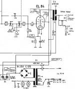
Appreciate the feedback all. Located a schematic. Looks like there are 4ohm and 7ohm taps on the opts.
Measured both opts, same results - about 1.5x greater voltage on the primary when feeding the secondary? All the transformers are removed and no longer in the circuit.
Measured both opts, same results - about 1.5x greater voltage on the primary when feeding the secondary? All the transformers are removed and no longer in the circuit.
Attachments
Last edited:
Something is amiss.
Wrong connections (several wires can be confusing).
Shorted turn(s)
Test Frequency too low for the drive signal impedance versus the inductance of the winding
Frequency way too high versus terrible leakage reactance
Frequency way to high and distributed capacitance way to high, versus a very high impedance signal source.
Maybe the transformer is not an output transformer.
You must measure both input and output voltages at the same time (if you did not already do that).
Secondary voltage = 1.5 x primary voltage.
1.5 x 1.5 = 2.25
Primary Z is only 2.25 times the secondary Z.
Not good as an output transformer for most tubes.
Well, maybe for the special 800 Ohm speakers that some radios had.
Is it a Power Transformer?
We need to solve the problem with only 2 more posts (10 posts).
Last edited:
The B+ rail voltage shown in the Löwe schematic is somewhat low. That rules hybrid bridge rectification out, as every last volt matters.
It may be possible to work around the "short" B+ rail by employing "fixed" bias O/P tubes. A C- (bias) supply disposes of the voltage drop in a self bias setup.
It may be possible to work around the "short" B+ rail by employing "fixed" bias O/P tubes. A C- (bias) supply disposes of the voltage drop in a self bias setup.
The B+ rail voltage shown in the Löwe schematic is somewhat low. That rules hybrid bridge rectification out, as every last volt matters.
It may be possible to work around the "short" B+ rail by employing "fixed" bias O/P tubes. A C- (bias) supply disposes of the voltage drop in a self bias setup.
Not sure why the schematic indicates 250vAC - I measure 310v on the power trans secondary.
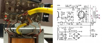
This iswhat I make of it as most probable connections.
Looking at the values in the schematic the EL84 is used as a EL41.
Fhat means 4W out and a 7k opt.
Mona
Thanks Mona, if that is the case then, to my query re: suitability for use to build the RH84 circuit which calls for a 5k opt? so these opts will not work?
Not sure why the schematic indicates 250vAC - I measure 310v on the power trans secondary.
What you measure will droop under load. An "ancient", low cost, AC VOM is 10000 Ω/V. That's not particularly good, but far from terrible. A modern DMM or old VTVM presents several million Ω to the winding. A rectifier/filter setup feeding signal circuitry that's operating is a very different "kettle of fish".
Also, today's higher average AC mains voltages causes a small uptick in the measured value.
Eli, I need help in interpreting your comment, I understand there will be drop under load. I should be able to work with this power transformer to get the required B+ of 300v.
(250 VRMS) (21/2) = 353.6 Vpeak Therefore, with decent construction, you should be OK.
CLC filter the "raw" B+ produced by the bridge rectifier. A low cost Triad C-14X choke will do a decent job of "decoupling" the reservoir cap. from the 1st filter capacitor. Use a good sized part in reservoir position, for reasons of energy storage and ripple suppression.
The exact value of the 1st filter cap. must be determined experimentally, with the PSU under load. A capacitance sufficient to keep the rail voltage up, and no more, should be employed. A comparatively small value in the 1st position minimizes the I2R heating that occurs in the rectifier winding.
Thanks Mona, if that is the case then, to my query re: suitability for use to build the RH84 circuit which calls for a 5k opt? so these opts will not work?
Hi,
You wanted to build this amp for simplicity, to make your life simpler just buy some decent Output Transformers. By doing so you’ll have a good match with your speakers and you won’t wonder about the OPT connections.
BR
Eric
I think the answer to the original query is, yes, the OPTs will work, but they may not be optimal.
There is a tapped primary in Mona’s picture, with part of the primary being used for CFB. Presumably if the tap was not used the impedance would be closer to 9k (which might open up other possibilities).
There is a tapped primary in Mona’s picture, with part of the primary being used for CFB. Presumably if the tap was not used the impedance would be closer to 9k (which might open up other possibilities).
@slave2music
2X of these wired in series will provide a reasonable "dummy" load of your B+ PSU, during the "breadboarding" process. Mount the resistors on some sort of sheet metal, to help dissipate the substantial amount of heat you will generate.
This item should be satisfactory as the reservoir cap. in the PSU.
Start with a 2.2 μF./450 WVDC part in the 1st position and measure the voltage drop across the 3000 Ω resistance. If you get < 300 V., the amount of capacitance in the 1st position has to increase. When you find an amount of capacitance that yields 300 V. or a little bit more, STOP.
BTW, the best results for this empirical process are obtained when the filament winding is also subjected to an appropriate "dummy" load.
The voltages in the schematic are referenced to ground measured with a 33k/V instrument.
The 250V~ must then be the measured voltage across a diode in the bridge.
Those analog meters measure the mean voltage with a dial translated to RMS in the supposition it is a sine wave input.The measured voltage, in this case, doesn't mean much.
The rectified voltage seems to be 268V (not very readable) so the transformer output is more or less 200V~RMS.
Mona
Mona,
The OP measured the unloaded voltage of the rectifier winding at 310 V. Of course, that number will drop, when the winding actually has to do some work.
IMO, getting a functioning 300 VDC rail should not be particularly difficult.
The OP measured the unloaded voltage of the rectifier winding at 310 V. Of course, that number will drop, when the winding actually has to do some work.
IMO, getting a functioning 300 VDC rail should not be particularly difficult.
- Home
- Amplifiers
- Tubes / Valves
- Advice on first RH84 build - are these transformers suitable?