So my Harmon Kardon 22 was working well before being out into storage for a couple of years (3 years maybe). Pulled it out of storage to hooked it up only to find it goes immediately into protection as soon as it is powered on, with or without speakers connected.
A bit of research has lead me to believe that replacing the 33uf10v capacitor on the protection circuit (c11) would be a good place to start.
I would like to learn more about troubleshooting this amplifier though rather than just following internet advice. Measuring voltages, other caps to replace, adjusting the bias. Where is a good resource for learning this?
Also is it worth putting time and resources into this amplifier? How does it hold up today?
Some "swear by it " ( not at it ) other swear at it - complaining- "bright /thin " .
Faults--yes your fault "goes into protection mode " --several -- 4 smoothing capacitors in power supply go faulty and loudspeaker cable connectors "rotten/rubbish " also other faults .
Those that like it practically drool over it.
Change the smoothing capacitors first if repairing it.
Nobody complained about the capacitor you quoted but there again they weren't on technical websites .
Not dear to buy now so don't spend more than $200 (US ) on it.
All say don't buy the preamp -rotten equalization.
I'm going to request a bit of hand-holding here as I don't fully understand the engineering behind the design. When you say smoothing capacitors so you mean the circuit that limits spikes during power on/off?
Also, any assistance with some other priority caps would be helpful. Ones in the signal chain perhaps. My plan is to get it running and start replacing them slowly over time.
Also, any assistance with some other priority caps would be helpful. Ones in the signal chain perhaps. My plan is to get it running and start replacing them slowly over time.
Code:
Cap#  Value    Voltage    Location
C11   33 µf    10v        Main Board
C12   33 µf    50v        Main Board
C35   1 µf     100v       Main Board
C417  10 µf    16v        Main Board
C418  10 µf    16v        Main Board
C423  10 µf    16v        Main Board
C424  10 µf    16v        Main Board
C425  10 µf    16v        Main Board
C426  10 µf    16v        Main Board
C427  10 µf    16v        Main Board
C428  10 µf    16v        Main Board
C31   100 µf   25v        Protection Board
C33   47 µf    16v        Protection Board
C413  470 µf   100v       Pre Driver Board
C414  470 µf   100v       Pre Driver Board
C415  470 µf   100v       Pre Driver Board
C416  470 µf   100v       Pre Driver Board
C437  330 µf   16v        Pre Driver Board
C438  330 µf   16v        Pre Driver Board
C405  330 µf   16v        Pre Driver Board
C406  330 µf   16v        Pre Driver Board
C411  47 µf    10v        Pre Driver Board
C412  47 µf    10v        Pre Driver Board
C401  100 µf   10v        Pre Driver Board
C402  100 µf   10v        Pre Driver Board
C431  10 µf    16v        Pre Driver Board
C432  10 µf    16v        Pre Driver Board
C85   330 µf   16v        Input Jack Board
C86   330 µf   16v        Input Jack Board
C87   330 µf   16v        Input Jack Board
C88   330 µf   16v        Input Jack Board
C83   2200 µf  6.3v       Input Jack Board
C84   2200 µf  6.3v       Input Jack Board
C81   100 µf   10v        Input Jack Board
C201  470 µf   25v        Relay board
C202  220 µf   10v        Relay board
C203  220 µf   10v        Relay board
Attachments

The protect light comes on on start up and after several seconds goes out leaving the operating red lights on depending on if its set to 4 or 8 ohm operation. If this isn't what yours is doing there is past evidence that cap c11 has brought them out of protect.I would change that one with similar specs first.
Quick update. I replaced C11 with a new 33uf 25v cap and it came out of protect mode 🙂
Just running it through its paces now and will do a DC balance adjustment later. Might have to read up a bit more before I attempt to test and adjust the idling current.
Just running it through its paces now and will do a DC balance adjustment later. Might have to read up a bit more before I attempt to test and adjust the idling current.
Good news. I have replaced all the electrolytic caps except the large 10,000 uf ones . I did it in stages and double checked everything then listened for a couple days then did another section .It made a very nice improvement. Also look out for cold solder joints I had several but it was still working fine. You will need some 100 ohm resisters to do the idle current like the manual states. Good luck.
When you all do you mean every last one? I wasn't planning on doing anything related to the display panel.
Any insight into where you noticed the biggest improvement? I was thinking of doing the rest of the mainboard next as they are easy to get to then moving on to the driver board. Any caps, in particular, that would benefit from splurging a bit? I've read the C401 and C401 might benefit from a higher quality cap.
Any insight into where you noticed the biggest improvement? I was thinking of doing the rest of the mainboard next as they are easy to get to then moving on to the driver board. Any caps, in particular, that would benefit from splurging a bit? I've read the C401 and C401 might benefit from a higher quality cap.
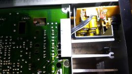
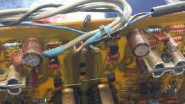
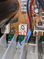
Sorry ,i didn't touch that area it works fine. You will need to be aware of size and lead spacing to get proper fit in some areas. I wasn't concerned of cost ,I find their cheap enough as is. I will post some picks what i used ,doesn't mean I picked the only choices.
Attachments
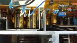
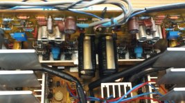
A couple more for reference. I used an Elna Similic ll in that spot c401 i think.If possible go up one voltage at least in most areas.
Attachments

Last edited:
Another update. I have been driving some Kef Q100's (8ohm) for the last hour at a low to moderate volume and the amp has been heating up. It finally got hot enough to go into protect mode. Both heatsinks appear to be approximately the same temperature. I'm hoping it isn't a bad transistor. I know these amps run hot but I never had an issue driving my Accoustats with them for extended periods which are notoriously demanding to drive. Looks like I will need to start with adjusting the bias.
Unfortunately I won't be able to diagnose anything like that. I would make sure its set to 8 ohm on the back and front push button. Then check the idle current. At the proper 8 mv mine only gets warm now.
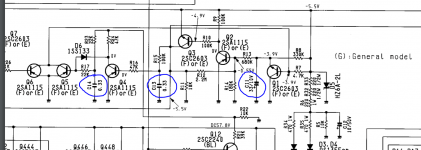
Just reading on another forum right now, in a thread you participated in lol, about how to measure the bias directly from the emitter resistors. Just trying to make some sense of it all before I give it a go. According to the thread, this is a better way of measuring the bias instead of attaching the 100 ohm resistors.
It's all a learning experience for me 🙂
It's all a learning experience for me 🙂
Yes i remember reading that I didn't attempt it .lol I bought the resistors and did it the way the service manual says its bang on 8 mV each channel. You need to adjust the offset also after and during it takes a while to get it.good luck
I took a stab at doing some adjustments. I let the amp warm up for about 20-30 minutes before taking a reading at the speaker terminals start with the amp in 4ohm mode. The readings were unstable but averaged around 40mV. I was able to dial them back to about +/- 5mV but there were still quite unstable. Switching over to 8ohm, the readings were about +/- 10mV. I decided to move on to the idling current adjustment.
I started with the right channel. The initial reading was around 50mV and I adjusted the potentiometer all the way but was only able to lower it to 19mV. The left channel was only off by a few mV and I was able to adjust it right to 16mV.
I went back and checked the DC balance. Reading at the terminals was now very stable and I was able to adjust the voltage to read 0mV at 4ohm and +/- 5mV at 8ohm.
I hooked it back up and played some music for only a few minutes before noticing the front heatsink was cooking, very very warm. The rear heatsink had barely warmed up by comparison.
Did I mess something up with the idling current adjustment? Is the issue with VR404 being outside the range of adjustment and indication of a broader problem? Or maybe I am misunderstanding what it means by TP1 to TP2 and TP2 to TP4 add up to 16mV.
Either way I will have to try again as I am worse off than before.
Ok I've had some success, updating for anyone following or happens to stumble across this thread a few years from now.
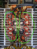
I gave up on the procedure detailed in the service manual and measured each power transistor emitter resistors instead. It took some time to get it dialed in and the heatsinks on the 22 make access a bit of a pain but I got things in much better shape.
I started by measuring the power transistor emitter resistors closest to the potentiometer and adjusting it as close as possible to 16mV and switch to measuring the resistor furthest away trying to average the two to be around 16mV. In my case, after adjusting the potentiometer to about 16mV the second read 19mV. I made adjustments so the furthest resistor was reading about 17.5mV
Before measuring the two middle resistors I started the same procedure above on the other channel. I didn't have as much luck with this one but managed to get readings of 19.5 and 14.5mV. Then I measured the middle two resistors on each channel to see where they fell. I found that all readings fell between 14-20mV, not perfect but reasonable.
I redid the DC balance. One channel was way out from my previous adjustment done with the previous idle current adjustment, around 550mV at 4ohm. I was able to get things dialed into about +/-10mV at 8ohm.
Been playing music for the last hour and both heatsinks are equally warm but not hot to the touch.
Attachments
Last edited:
- Home
- Amplifiers
- Solid State
- Harmon Kardon Citation 22 repair/rebuild worth it?