Hi All. I picked up a MC cart for my TT and also was given a pair of no name step up transformers to build a SUT for the new cart. He didn't know anything about them and so I would like to test them to see what ratio they are.
How do I do that without burning them up?
How do I do that without burning them up?
Attachments
Last edited:
The TM** type number reminds me of Amplimo, but I can't find a TM02 on their site.
Apply a small (few millivolt) AC signal to one side and see what comes out on the other side. What equipment have you got to measure small AC voltages? Oscilloscope, soundcard? When you measure the primary and the secondary voltages with the same instrument, scale errors drop out of the equation.
By the way, when you connect a multimeter set to one of its lower resistance ranges to a signal transformer, you may have to demagnetize it afterwards to get the even order distortion back to normal.
I have a Fluke 189 which can measure millivolts. I just don't know what to use to put millivolts into it. Any suggestions?
Maybe a CD player, test CD and a voltage divider made of two resistors, for example 10 kohm and 100 ohm. Of course CD players are obsolete technology, but any other line level source that can produce a sine wave with a voltage divider behind it will also do the trick. In principle you could even use a mains transformer plus voltage divider.
By the way, doesn't mains hum mess up the measurements when you measure millivolt levels with a multimeter?
By the way, doesn't mains hum mess up the measurements when you measure millivolt levels with a multimeter?
Last edited:
How about a wall wart?
I'm looking at the one for my phone charger:
Input: AC 117V, 60Hz, 80mA
Output: AC 6V, 300mA.
You'll have to cut the plug on the output, add some alligator clips or similar to connect to the transformer under test.
You can connect an o-scope to the output of the transformer and see what voltage output you get.
A very-hot moving-MAGnet signal is 20mV-50mV. Say 10mV to stay out of trouble.
Then a moving-COIL signal is around 1/10th of that or 1mV.
WHY do we even think this is a phono transformer? My bet would be microphone or even a geo transformer from oil exploration.
Then a moving-COIL signal is around 1/10th of that or 1mV.
WHY do we even think this is a phono transformer? My bet would be microphone or even a geo transformer from oil exploration.
I have a box full of wall warts with different ratings. There are some as low as 10mV, Marcelvdg...
I have a box full of wall warts with different ratings. There are some as low as 10mV, Marcelvdg...
Well if I don't have one like that I can find one for a buck at the local Goodwill.
I have a Fluke 189 which can measure millivolts. I just don't know what to use to put millivolts into it. Any suggestions?
Play this 1kHz tone through your phone or any mp3 player.
https://www.mediacollege.com/audio/tone/files/1kHz_44100Hz_16bit_30sec.mp3
Headphone output will be typically between 100mV and 200mV RMS
Use a 1k:100 ohm attenuator to get 10/-20mV for transformer primary, measure secondary mV
Or 1k:10 ohm for 1-2 mV if that floats your boat 🙂
If you REALLY want to do it the way the white lab coat guys do, use a variable attenuator (they use precision resistors, a resistor box or a precision calibrated pot) so recovered audio after transformer is same as generator output, then attenuator ratio = transformer voltage ratio.
Clever, huh?
Almost forgot: set player to "repeat" or "repeat one" because this is only 30 sconds long, so you get a continuous tone (with a small glitch every time it restarts).
If you prefer 440Hz:
https://www.mediacollege.com/audio/tone/files/440Hz_44100Hz_16bit_30sec.mp3
Last edited:
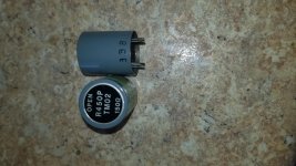
djn - are there any markings on the bottom of the transformer? Also perhaps the side? The upright transformer in your photo seems to have a sticker...?
Why can't you simply hook it up to your signal generator and input 1volt to determine the output voltage the turns ratio and db gain. With the coils impedance can't you figure the cartridge loading capability?
After determining its output capability why not run a square wave into it and look at the output?
After determining its output capability why not run a square wave into it and look at the output?
- Home
- Source & Line
- Analogue Source
- how to test a step up transformer