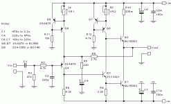
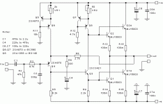
Is it possible to add more output transistors to an output stage in parallel to increase the current capability of the amplifier?
An example would be the JLH design revised by the Sound-AU guy. (schematic attached) There he used an MJ15003 as the outputs (refering to schematic 3, high power version) what if I just added another pair keeping all values that same? I'm not modifying his design I'm just using his design as an example, it just happens to be what I last read about.
Specific question
1. Is there changes needed for the bias design to keep the outputs biased to the original design specifications?
2. Is there a need to increase the heat sink design for any reason other than using lower impedance loads resulting in increased current demand.
3. Is there changes needed to the emitter resistance and wattage used?
4. Does the driver stage need to be modified to handle increased current from the output stage. If so can a driver stage transistor of transistors be paralleled as well?
5. Is there any other changes needed that is not considered by the questions asked above?
Attachments
While paralleling transistors is a way to increase current handling I suspect that here you will not gain anything... because the JLH is a Class A design and when set up properly is running at the correct bias needed to support the expected load current.
In other words it isn't like a Class AB amp where a sudden transient can demand more current. In the Class A amp that transient limitation is already in place by the bias setting.
If you reduce the load impedance the amp just runs out of current to deliver and clips, the current can not keep increasing as the load impedance falls as does the Class AB design.
Unless you intend deliberately making a higher power version that will be biased accordingly and such that a single pair can not handle the power (heat) then it makes little sense.
The driver stage has to supply the current needed to achieve the bias you want to set and so that same condition exists whether you bias a single or multiple pair of outputs. In other words for the Class A amp a single pair biased to 2 amps will place essentially similar demands on the driver as a set of four pairs biased to 500ma per pair.
Okay, that makes sense Mooly. I do understand the difference between the classes.
To summarize, If I were to add another pair to the output I would keep the bias the same and simply provide more cooling for the increase or double of current capability. As for the Driver, I would increase the current capability to double for the added pair of outputs. The power supply must be increased by double for mono and 4 times for stereo for the increase of current capability.
Simpler terms for my sake, doubling outputs means, doubling driver capability and doubling the mono power supply
The current is divided between two transistors. Base current also. The driver must provide the sum of the currents. Set the current with trimmer 2. A preliminary calculation is required.
To summarize, If I were to add another pair to the output I would keep the bias the same and simply provide more cooling for the increase or double of current capability. As for the Driver, I would increase the current capability to double for the added pair of outputs. The power supply must be increased by double for mono and 4 times for stereo for the increase of current capability.
Simpler terms for my sake, doubling outputs means, doubling driver capability and doubling the mono power supply
If you have a single pair biased at 2 amps you have a given heat dissipation (depends on supply voltage) and you have set a limit on how much current can be driven into the load by your choice of bias current.
If you add another pair and keep the total bias the same (so now 1 amp per pair) then nothing has changed apart from each pair dissipating only half the previous level of power.
If you add another pair and increase the bias to 2 amps per pair then you have doubled the total heat dissipation and provided the ability to deliver more current into a lower impedance load. The driver has to supply twice its original current as it now supplies two pairs of outputs and so the driver dissipation doubles. In the original JLH that dissipation is in the resistor network feeding the upper transistor.
Not just the driver transistor, either.
If you want double the output, you have to double the quiescent current in the class A design as Mooly pointed out. That requires doubling the current in the driver, but that then has a knock-on to the input transistor, which also has to drive more current.
The circuit you posted in #1 may work, though, if the MJ15003's have a high gain at moderate currents (~1A) so that two of them can work without requiring too much current in the driver. So I would say that the answer to your question is "it depends", and as OldDIY mentioned, a quick calculation of what the requirements would be are really needed.
- Home
- Amplifiers
- Solid State
- Question about SS output stage?

