Hi guys.
I'm trying to repair a Luxman MB-3045 monoblock (I have another working MB-3045 to compare).
The power transformer died (exploded or melted), so I got it rewinded and already installed it. Still trying to find the right diodes for the power supply, the original ones are unrecognizable, and the ones in the working amp apparently have been discontinued for a while.
All multi section can capacitors measure ok when disconnected, but I have a short somewhere when I connect them back into the circuit.
Is it possible that the output transformer also died when the power trafo went south?
Thanks in advance.
It seems like a bit of a pain to find a complete schematic for the amp, do you have one to post?
To check the output transformer, find the B+ connection and measure the DCR between it and each output tube plate. The DC resistances won't be perfectly identical, but they should be pretty close. You luckily have another amp to compare it to!
I would absolutely assume that both amps need to be recapped if they are running original power supply caps. That's very likely the cause of the destroyed power transformer.
Those are some complicated OTs! Still, the B+ to plate sections would be the ones that would give you problems, and the DCR would be funky if the OT is damaged.
The amp has been converted to KT-88 power tubes since the original 8045G tubes are not longer available. There are 4 caps C201-C204 22uF in the schematic. These have been changed to 47uF/450V.
audiowize: how would I measure DCR in this amp?
audiowize: how would I measure DCR in this amp?
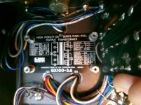
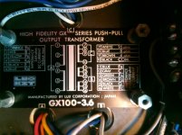
BTW, this OT has a few wires with different color than indicated on the tag.So yeah, its complicated. Sounds a little bit smoother that PITA...
The schematic and the label on the transformer tell which wires are connected to the same winding. Measure those.
I have problem with measuring the wires.
Since I have the working amp for comparison that is exactly the same model, it seems that the OTs have slightly different pinouts. On the picture you can see the pinout which checks out for the working amp, but the transformer on the "not working" amp has one wire in section "B" that is white with a pink stripe, and another one that is ether grey or brown (color fainted due to age or temperature, so it's hard to determine). I guess I have to pull every wire on this section on both amps to measure them correctly. Connected in the circuit they give different values, while all components measure the same.
I wish I have some explaining literate on this particular output transformer...
Attachments
I just checked the choke coil on both amps. The working one measures 31 ohms against the non working one with 4.3 ohm. I'd guess the last one is toast. But it is not shorted against the inclosure of the choke, and it still has a few ohm that are within the tolerance for choke coils.
You can run the amp without the bad choke in the circuit, and with the two filter capacitors in parallel.
As long as the bad choke isn't shorted to ground, just connect the two hot capacitor terminals together,
which shorts out the choke, and leave the choke in place. There still won't be any audible hum.
I'd do the same in both amps. My pair of these amps ran like that for years without any problems at all.
Last edited:
- Home
- Amplifiers
- Tubes / Valves
- luxman mb 3045 with blown power transformer