Good day gents,
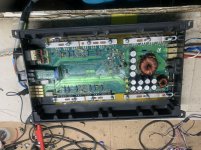
Recently completed rebuilding the right channel and minor PS repair (FETs replacement only) in a kicker zr360.
On initial power up I get about 19v dc across the speaker terminals and it quickly settles to around 210mv (this is in bridge mode).
All other power ups after this there’s only the 210mv across the speaker terminals.
If I leave the amplifier disconnected and aside for a few hours, if I power up the amplifier it repeats this, it has about 19vdc across the speaker terminals which quickly settles and all other power ups after this it’s around the 200mv level (bridge mode).
Anyone ever came across this before?
Attachments
Sorry about that, bridge mode was the last bit of testing I did, and I tend to do all final test in bridge mode as I did some final testing on a few others.
On the repaired channel there’s about 17vdc and the unpaired channel, 2vdc.
On the repaired channel there’s about 17vdc and the unpaired channel, 2vdc.
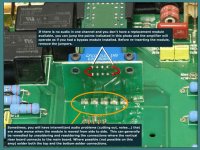
Pull the module and jump the connections with wires as shown.
Does that make a difference on the output DC offset?
Does that make a difference on the output DC offset?
I pulled the modules and jumped the wires, left channel measured 11v and right channel 8vdc.
Both subdued quickly.
I only get this dc at the speaker terminals, if I leave the amplifier disconnected for a period of time and then power it up. Once connected to the PS, repeated cycles there's no noticeable (under 200mv range) dc at the speaker terminals.
Both subdued quickly.
I only get this dc at the speaker terminals, if I leave the amplifier disconnected for a period of time and then power it up. Once connected to the PS, repeated cycles there's no noticeable (under 200mv range) dc at the speaker terminals.
What's the resistance from the input RCA shields (nothing plugged in) to the non-bridging speaker terminals?
If you touch a load across the terminals for each channel, does the offset drop to near 0v or does it cause the amp to draw additional current?
You seem to be on something here Perry.
I connected my dummy load across the R channel and powered up I measured 1.20V which quickly dissipated. I switched to the L ch and this measured 0.31v, and this too was decreasing in value. Neither instances drew surplus current.
I've left it unpowered aside, I wanna retry later on.
(these tests thus far are with the XO module out and bypassed, red bridges/jumpers in place as in the pic)
Do you have positive and negative rail voltage?
Do you have positive and negative regulated voltage on the power supply pins of the op-amps?
If so, post the DC voltage on both TL431s in the output stage. Black probe on the negative rail.
Do you have positive and negative regulated voltage on the power supply pins of the op-amps?
If so, post the DC voltage on both TL431s in the output stage. Black probe on the negative rail.
Do you have positive and negative rail voltage? yes: 70.6vdc
Do you have positive and negative regulated voltage on the power supply pins of the op-amps? yes: +/- 15vdc
If so, post the DC voltage on both TL431s in the output stage. Black probe on the negative rail.
R (U3)
1 -67.1
2 -69.7
3 -69.6
4 27mv
5 96mv
6 -69.1
7 -69.0
8 -66.0
L (U6)
1 -67.9
2 -69.9
3 -70.0
4 51mv
5 230mv
6 -70.5
7 -70.6
8 -67.7
I think you had it on ground, not the negative rail.
As a side note, ±70v seems excessive for this amp. Re-check.
As a side note, ±70v seems excessive for this amp. Re-check.
Last edited:
This amp has +\- 35v rails.
I measured with the black probe on the negative rail.
With the black probe on ground, all the measurements above are halved.
(PS ground ties to the non bridging speaker terminals)
I measured with the black probe on the negative rail.
With the black probe on ground, all the measurements above are halved.
(PS ground ties to the non bridging speaker terminals)
I can't understand what's happening. If you have a -35v rail and your black probe was on that rail, how could you read 70v below the -35v?
What's the DC voltage between the primary ground and the non-bridging speaker terminals?
What's the resistance (no RCAs plugged in, no power) between those two points?
What's the DC voltage between the primary ground and the non-bridging speaker terminals?
What's the resistance (no RCAs plugged in, no power) between those two points?
- Home
- General Interest
- Car Audio
- Kicker zr360