Hi, I added you zip to JLCPCB and after loading I get a lot of options. Is there any option needed? Of is everything OK with the standard settings as loaded? I’m not too familiar with all the terminology and never ordered PCB like these before.
Regards, Gerrit
Regards, Gerrit
Just keep the standard options.
But you can change the color of the board and/or top documentation.
I like black PCB with white text, but that is personal.
And use standard economy shipping to stay below €22,- or else you have to pay BTW and other cost at customs.
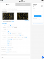
See sample below.
But you can change the color of the board and/or top documentation.
I like black PCB with white text, but that is personal.
And use standard economy shipping to stay below €22,- or else you have to pay BTW and other cost at customs.
See sample below.
Attachments
I just ordered the PCB’s. I’m not in a hurry, so I chose the slowest and cheapest delivery possible. Next thing I need is 5 turntables (5 PCB’s 😀).
Which transformer do you use? Do you seperate the PSU and the electronics?
Regards, Gerrit
Which transformer do you use? Do you seperate the PSU and the electronics?
Regards, Gerrit
As in the picture I had the transformer custom made at Toroidy in Polen.
Secundairy = 1 x 230v 50mA, 1 x 12v 1A, 2 x 15v 50mA.
Transformer is on top of my preamp housing.
Secundairy = 1 x 230v 50mA, 1 x 12v 1A, 2 x 15v 50mA.
Transformer is on top of my preamp housing.
Attachments

Last edited:
Good work!!!! You should have defined all those PL markings instead of input-output etc.Can you do that?Thanks a lot
For using LM317/337 you must place a voltage divider(pin 1) for the desired(+-15V). The connection shown on your schematic is for LM7815/7915 only. There is an online calculator for the resistors values of the voltage divider. The circuit as it stands gives only 1,25V at the output.Which voltage regulator is shown at the schematic? Because Lm317 and LM7815 have different pinouts.Please check it outFor a lower budget you can use other regulators as the TPS board regulators like LM317/337 or other.
Sorry but I see some omissions. No HV power on plops as the output caps charge?! The resistors to provide a path to GND are missing so the charging will be via the connected device which might be bad for its health if it is modern electronics. When a device is not connected the charge could be via the user when he/she changes RCA cables and accidentally touches the middle pin. When that doesn't happen plugging in the RCA cables into a preamp/power amplifier causes the charging to happen via that device. When powering the device off the caps will keep their charge as well as there is no path to GND which poses new challenges with regards to user safety ... ah well you understand what I mean. Just 2 resistors 475 kOhm and things are relatively safe and according standard practice. Muting to GND is a choice, safety is not. Muting to GND would also improve safety as there will be no charging/discharging at the outputs.
It was a very long time ago that I built phono preamps but normally one uses input load selection (R, C) to adjust for the type of MM element isn't it? In todays polluted environments maybe a ferrite bead at each input wouldn't hurt.
It was a very long time ago that I built phono preamps but normally one uses input load selection (R, C) to adjust for the type of MM element isn't it? In todays polluted environments maybe a ferrite bead at each input wouldn't hurt.
Last edited:

If some like, you can ad resistor ad the output and gnd( as Jean Paul stated) . I have connect it to a passive preamp with 20k input impedance. Here no problem with plop or high voltage charge.
And yes i have a input load selection board before this phone preamp, like i did with the phonodude koifarm edition.
R31 is part of the RIAA filter feedback track. It sets the gain((R29+R20) /R31*30/10). No audible noise.
These is the phono preamp i still daily use.
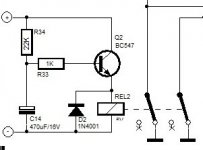
Below simple startup delay mute circuit to connect to heater supply. Relayswitches between output and gnd.
And yes i have a input load selection board before this phone preamp, like i did with the phonodude koifarm edition.
R31 is part of the RIAA filter feedback track. It sets the gain((R29+R20) /R31*30/10). No audible noise.
These is the phono preamp i still daily use.
Below simple startup delay mute circuit to connect to heater supply. Relayswitches between output and gnd.
Attachments
Last edited:
You mean the phenomenon does occur but in your specific case with a passive source selector/volume controller it does not cause any damage.
Tip: a design that will also be built by others should be usable in various scenario’s and it should be safe both to humans and equipment. Safety is not debatable. It would be wise to have designs checked by people you know that have that competence before publishing. This is constructive criticism meant in the interest of all involved.
Tip: a design that will also be built by others should be usable in various scenario’s and it should be safe both to humans and equipment. Safety is not debatable. It would be wise to have designs checked by people you know that have that competence before publishing. This is constructive criticism meant in the interest of all involved.
Last edited:

That seems more complete. Small imperfection is omission of stop resistors at the outputs that have more than 1 purpose. Can you mention 3 purposes?
The GND reference resistors also lack. Please notice what happens if the relay contacts might fail.
As mentioned before, I can not imagine this preamp not picking up garbage. Stop resistors at the inputs and/or ferrite beads should be tried and results should be measured. Your environment may be HF/RF free, that of the builder maybe is not.
Last edited:
I used tps7a47/33 regulators on mini PCB. For lm317 or 7815 you have to improvise as you to
I used tps7a47/33 regulators on mini PCB. For lm317 or 7815 you have to improvise as youW
What is the purpose of the 12 volts power supply? I hope not for the tube heaters as all the tubes at that schematic use 6,3V.
Filaments are in series as can be seen on the PCB. It is only an error in the drawing/schematic. Pin 9 of U4a is called "H" and it is connected to pin 1 of U4b also called "H". Same counts for U3a and U3b.
Speed from idea to product is admirable but then the risk is small or even large mistakes. We all had that IC in mirror view drawn on a PCB once. At least once that is.
Speed from idea to product is admirable but then the risk is small or even large mistakes. We all had that IC in mirror view drawn on a PCB once. At least once that is.
Last edited:
When I am back from vacation I shall make the advised changes regarding safety and pin description. And update schematic and PCB.
In a Rev. 2 of the PCB pads for 7815/7915 could be added in parallel to the existing footprints of the regulators. Or the better LM317/337 PCB pads and a handful of parts. Right now the board accepts neither of these mentioned regulators which will create confusion. Apparently one must use LDO regs on adapter PCBs with that specific and incompatible pinout/layout.
Now if you wish to have it checked before publishing I am willing to do that otherwise it will be unbalanced. If one criticizes one should add something useful.
Now if you wish to have it checked before publishing I am willing to do that otherwise it will be unbalanced. If one criticizes one should add something useful.
Last edited:
- Home
- Source & Line
- Analogue Source
- Hybrid phono preamp