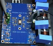
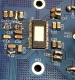
Hey folks, I have been bangin' my head for days now trying to start my 3255. Firstly, I believe I have blown my first IC by slipping the probe and shorting internal regulator output, so all regulator voltages were close to 0 as a result. After replacing the chip, voltages are now ok according to the datasheet, but I am still getting erratic behavior at the outputs.
This is my first 3255 build, so not sure if my expectations are correct, but I believe I should get it working with attached schematics as a minimum.
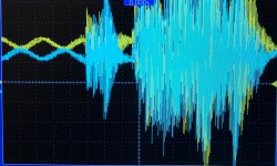
What I have now after boot, is CLIP_OTW lit all the time. A/B outputs are giving out something that resembles sine wave, and from C/D, only C has sine wave at the output. Any help is appreciated.
Attachments
That's because there is another 43K underneath 🙂) in parallel
VDD = 12.15
AVDD = 7.76
DVDD = 3.29
VDD = 12.15
AVDD = 7.76
DVDD = 3.29
These bootstrap caps C26 etc are not critical, you may use a single 68n as well. I use 100n on my board without problems.

I think it must be related to the way I’m measuring it. I don’t have a balanced source so I used single ended spdif dac with floating ground.
When I connect signal generator which is built into the scope, and not connect any ground from probes, I get a good sine output on each channel, except on D which is totally off.
- Home
- Amplifiers
- Class D
- Need help with starting up TDA3255


