Wanted to share my tube phono stage that I recently finished, along with a vintage turntable overhaul to match.
At a high level, it is a balanced input MC phono with Lundahl LL9226XL MC step-up transformers, CCS loaded LED biased triode-strapped D3a first gain stage, all-in-one passive RIAA EQ, CCS loaded LED biased triode-strapped EF86 second gain stage, direct-coupled to a AOT1N60 source follower output buffer. The power supply is in a separate chassis with raw DC B+ fed to the phono chassis via umbilical where it immediately hits a Maida regulator. Regulated DC from the heaters is also fed through the umbilical to the phono chassis, along with redundant chassis grounds.
In concert with this build, I restored a Thorens TD 125 MkII turntable. To match the phono, the tonearm was disassembled, cleaned, rewired with Cardas litz tonearm wire, and setup for dual 3-pin XLR balanced outputs.
I am having some technical difficulties with my measurement equipment, still working on a full suite of measurements, so I do not have them to share, sorry! I know people like to see the numbers. For what it's worth, subjectively, this TT phono combo sounds incredible. Spacious, dynamic, well-extended and very musical, leaving my digital setup buried in the dust! Oh, and hum free 😉
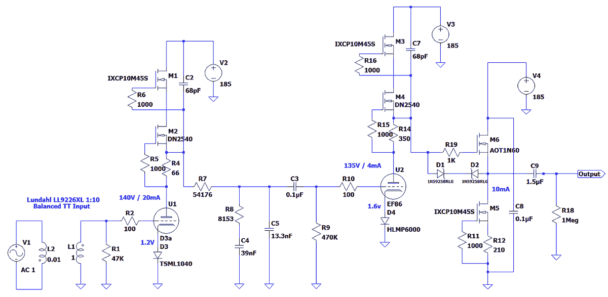
Here is the phono schematic.
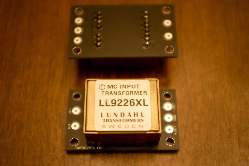
PCBs I designed for the Lundahl LL9226XL SUT. These are a new model from Lundahl, released earlier this year.
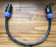
The eight conductor umbilical with Neutrik speakON connectors.

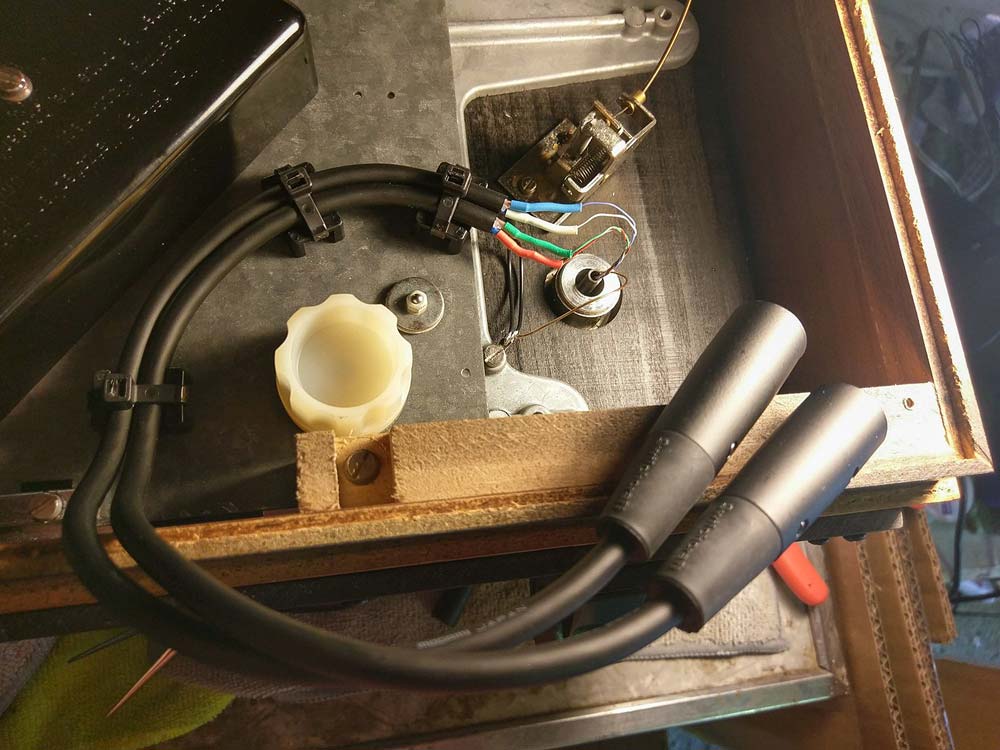
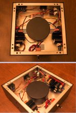
Interior of the turntable, tonearm wire exiting the base, terminated in 2x 3-pin XLR outputs with Mogami 2549 balanced cable.
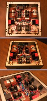
Power supply chassis interior.

Phono chassis interior.
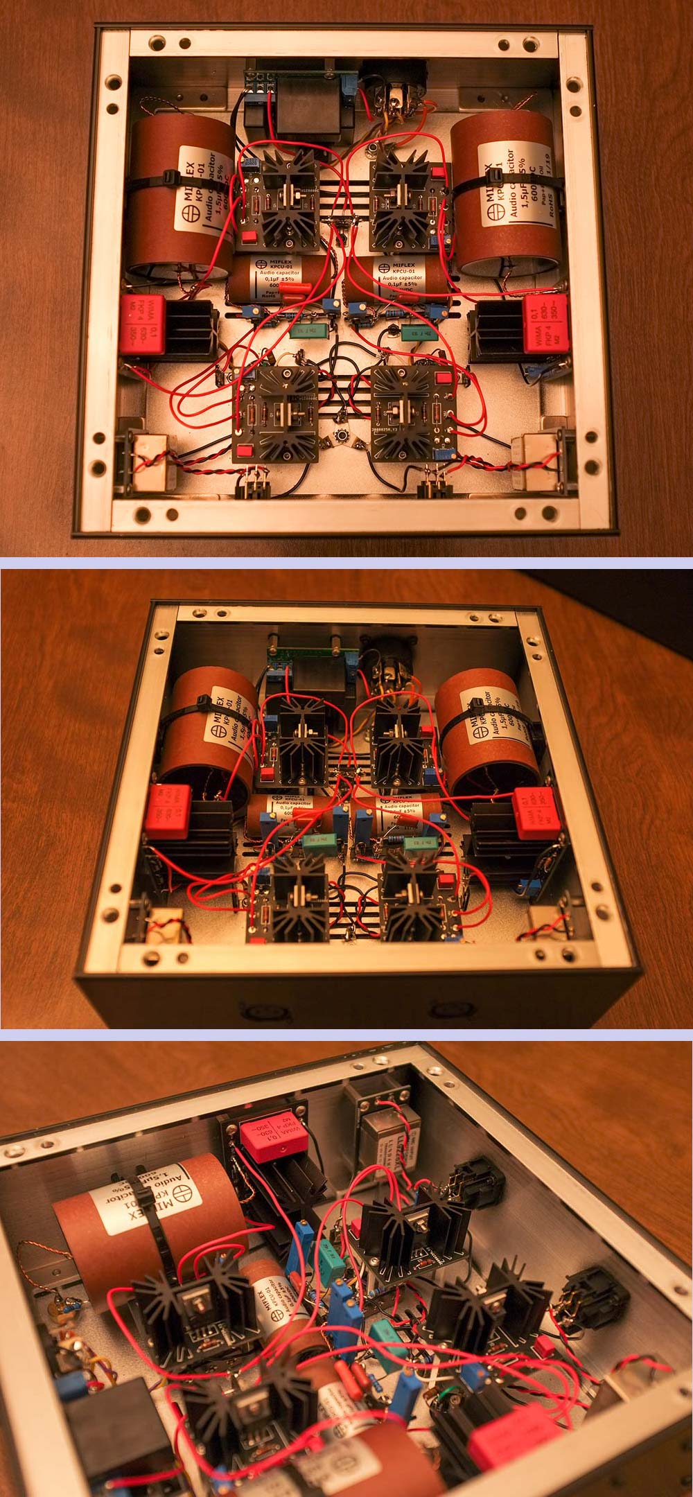
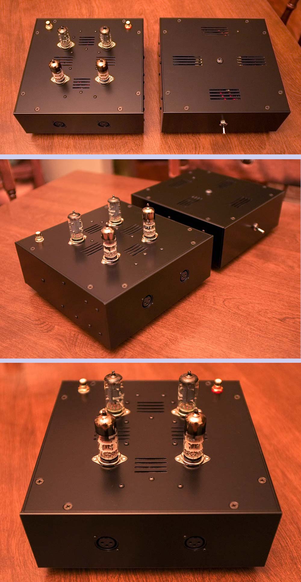
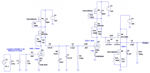
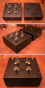
And the completed build. Chassis were machined for me by Landfall Systems, I then drilled and powder coated them in "Stone Black" from Prismatic Powders.
Sounding excellent in my system with a Hana EL cartridge.

Thanks for looking!
At a high level, it is a balanced input MC phono with Lundahl LL9226XL MC step-up transformers, CCS loaded LED biased triode-strapped D3a first gain stage, all-in-one passive RIAA EQ, CCS loaded LED biased triode-strapped EF86 second gain stage, direct-coupled to a AOT1N60 source follower output buffer. The power supply is in a separate chassis with raw DC B+ fed to the phono chassis via umbilical where it immediately hits a Maida regulator. Regulated DC from the heaters is also fed through the umbilical to the phono chassis, along with redundant chassis grounds.
In concert with this build, I restored a Thorens TD 125 MkII turntable. To match the phono, the tonearm was disassembled, cleaned, rewired with Cardas litz tonearm wire, and setup for dual 3-pin XLR balanced outputs.
I am having some technical difficulties with my measurement equipment, still working on a full suite of measurements, so I do not have them to share, sorry! I know people like to see the numbers. For what it's worth, subjectively, this TT phono combo sounds incredible. Spacious, dynamic, well-extended and very musical, leaving my digital setup buried in the dust! Oh, and hum free 😉
Here is the phono schematic.
PCBs I designed for the Lundahl LL9226XL SUT. These are a new model from Lundahl, released earlier this year.
The eight conductor umbilical with Neutrik speakON connectors.
Interior of the turntable, tonearm wire exiting the base, terminated in 2x 3-pin XLR outputs with Mogami 2549 balanced cable.
Power supply chassis interior.
Phono chassis interior.
And the completed build. Chassis were machined for me by Landfall Systems, I then drilled and powder coated them in "Stone Black" from Prismatic Powders.
Sounding excellent in my system with a Hana EL cartridge.
Thanks for looking!
Attachments


Last edited:

Very very nice.
Did you use any ferrite beads at the D3a pins ??
D3a is connected as triode,
how did you wire up with g2 and g3 ? g3 to ground or to cathode ??
Did you use any ferrite beads at the D3a pins ??
D3a is connected as triode,
how did you wire up with g2 and g3 ? g3 to ground or to cathode ??
Thanks all! g3 connected to cathode, g2 to anode with a 100ohm carbon comp. I did not use any ferrite beads on the D3a, just carbon composition grid stoppers on g1 and g2, haven't noticed any untoward noise/oscillations, but will keep those beads in mind if I see or hear anything concerning, thanks for the suggestion.
Beautiful! I built a D3A into a 5687 phonostage with excellent sound. Wired the D3A as a triode too.
Thanks much! Yes, lots of flexibility to adjust the gain of the phono with the second stage, bet the 5687 sounds great, I had a curiosity to try the triode-strapped EF86 given its fantastic linearity (the D3a too), happy to say the sound exceeds expectations 🙂 happy listening.
Looks fabulous!
Any issue with rehosting the pictures on our server so they don't go away in the future. This is too nice a build to evaporate into thin air in a few weeks or months.
Any issue with rehosting the pictures on our server so they don't go away in the future. This is too nice a build to evaporate into thin air in a few weeks or months.
Thanks, K! I appreciate it, and no problem at all, let me know if anything needs to be done on my end.
I always envy when I see a beautifully crafted piece of equipment. 🙂
What is the role of that 68pF across the CCS?
What is the role of that 68pF across the CCS?
The CCS's, together with the tubes, look more like hybrid mu followers.
Output impedance at the DN2540 source will be rather low.
Is the extra source follower output stage really necessary?
Output impedance at the DN2540 source will be rather low.
Is the extra source follower output stage really necessary?
Hi euro21 - thanks! The purpose of the 68pF capacitor is to limit HF bandwidth, less chance of an oscillation in the CCS, recommended to me in the past and have had success using it so far.
Hi daanve - you are right, the output impedance at the source of the DN2540 will be quite low but with some contribution from the internal resistance of the EF86. Low enough to omit the source follower buffer? I can't say, I did not investigate it, but I am happy with the results, so I will live and let live 🙂
Hi daanve - you are right, the output impedance at the source of the DN2540 will be quite low but with some contribution from the internal resistance of the EF86. Low enough to omit the source follower buffer? I can't say, I did not investigate it, but I am happy with the results, so I will live and let live 🙂
Nice design and impressive layout.
With regard to the 68pF cap; was that value recommended, or did you experiment to find the appropriate value, or is there a formula to calculate its size and bandwidth limiting?
Cheers
stay safe
tim
With regard to the 68pF cap; was that value recommended, or did you experiment to find the appropriate value, or is there a formula to calculate its size and bandwidth limiting?
Cheers
stay safe
tim
Sample: simulated CCS loaded D3a, CCS paralleled capacitor:calculate its size and bandwidth limiting?
Green: 0pF, blue: 68pF, red: 680pF, light blue 1n2.
Attachments

Thanks, Tim. The 68pF value was recommended to me, but euro21 is much more clever than I am and has illustrated the effect perfectly in LTSpice with the D3a specifically. A picture is worth a thousand words, as they say.
Hi daanve - you are right, the output impedance at the source of the DN2540 will be quite low but with some contribution from the internal resistance of the EF86. Low enough to omit the source follower buffer? I can't say, I did not investigate it, but I am happy with the results, so I will live and let live 🙂
It is super simple to investigate.
Measure loaded and unloaded output voltage and apply the well known formula.
My guess is that you don't need the extra source follower output.
Good engineering is to omit what you don't need.
Might sound (even) better too.
Output impedance of the input stage DN2540 is low enough to drive a much lower impedance RIAA stage. Might sound better as well.
To be clear, it is well built and executed, but within the same envelope there is IMO room for audible improvement.
Simple to calculate the output impedance, yes, and I do understand your point, it is well made. However I am not eager to re-evaluate the design and make changes at this time. I appreciate your devotion to sound engineering, I am no engineer and have only designed my first tube equipment in January of this year. So for now I will live with my perhaps flawed design. If the phono is rebuilt in the future, I will reference your post here and investigate taking the output from the DN2540 source, thanks for the feedback.
Last edited:
Nice looking build! Are the two boards with the common mode chokes on them your filament supplies?
- Home
- Amplifiers
- Tubes / Valves
- Sharing my Completed Tube MC Phono - D3a / EF86 / FET Hybrid