Hi,
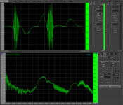
I’m worrying I have some kind of weird oscillation in my PP amplifier. As you can see in the spectrum around 8 kHz and around 16 kHz.
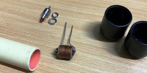
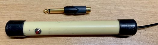
I’ve built an EMI sniffer, using some plastic pipe, two plastic caps, a miniature choke coil and a switch. The choke has a lot of very thin wiring, measures around 30 Ohm and 10 mH. The switch shorts the shielded cable, to stop measuring and show the noise floor. My sniffer is connected to my Steinberg UR242 USB external sound adapter.
My amplifier uses the ABS-Q auto bias module from audioamp.eu. At first the spectrum is more or less flat for about 2 minutes, only showing the usual 50 Hz hum and it's harmonics. The tubes warm up and settle for a specified cathode current. The oscillation starts when the blue led's on the ABS-Q turn on, which means the module is applying auto bias to the tubes.
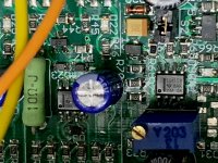
The oscillation is strongest around the LM358 chip.
I'm wondering if anyone has experienced similar things. What could I try to stop this module from oscillating?
Regards, Gerrit
I’m worrying I have some kind of weird oscillation in my PP amplifier. As you can see in the spectrum around 8 kHz and around 16 kHz.
I’ve built an EMI sniffer, using some plastic pipe, two plastic caps, a miniature choke coil and a switch. The choke has a lot of very thin wiring, measures around 30 Ohm and 10 mH. The switch shorts the shielded cable, to stop measuring and show the noise floor. My sniffer is connected to my Steinberg UR242 USB external sound adapter.
My amplifier uses the ABS-Q auto bias module from audioamp.eu. At first the spectrum is more or less flat for about 2 minutes, only showing the usual 50 Hz hum and it's harmonics. The tubes warm up and settle for a specified cathode current. The oscillation starts when the blue led's on the ABS-Q turn on, which means the module is applying auto bias to the tubes.
The oscillation is strongest around the LM358 chip.
I'm wondering if anyone has experienced similar things. What could I try to stop this module from oscillating?
Regards, Gerrit
Attachments
Last edited:
The module is stearing the grids of both finals over a 220K resistor, if I am right. 8KHz might be the sample frequency of this "miracle of ingenuity". Have you tried shielding the PCB?
Hi,
I’m using 100K to the grid. I have not shielded this PCB and that will me very difficult in my case. Could it be the wiring? Decoupling?
Regards, Gerrit
I’m using 100K to the grid. I have not shielded this PCB and that will me very difficult in my case. Could it be the wiring? Decoupling?
Regards, Gerrit
What does probing the bias voltage show? You connected the high value resistors right at the grids or distant, at the pcb? Does running a shielded bias cable to your grids sound acceptable?
The grid resistors are mounted directly at the tube sockets. I can try a shielded cable for grid and cathode. Hopefully tomorrow.
Regards, Gerrit
Regards, Gerrit
Please post a complete schematic of your amplifier.
Is it Fixed Bias with the ABS-Q changing the fixed bias level?
It sounds like the ABS-Q LM358 is marginally stable.
Complex circuits that employ negative feedback (error correction) to keep the Average
current stable just complicate the numbers of possibilities for oscillation.
Are you using a non-inductive power resistor on the amp output to test the output?
Oscillation can be a bugger to trace, after you've tried screening yon complicated doodad, try pulling it out and replacing with resistor/s. Sometimes oscillation can be caused by ground placement,move a grounding point 2cm and oscillation stops. Sometimes you can't find what's going on and the only answer is squash osc by de-coupling power supplies to yon board for instance or use a RC filter to kill oscillation. Hope that's makes sense.
Andy.
Andy.
There are many tradeoffs to all the various kinds of bias for the output tubes.
I found my favorite kind of bias is Individual Self Bias (Whenever possible):
Less output power (I am willing to make this tradeoff).
Stable Every Time. Wow!
Very Simple to calculate and to build.
Lower Cost.
Using reasonably matched output tubes, they have very well matched current in the two halves of the push pull output transformer primary.
When the Mains Power voltage goes up, or goes down, then . . .
The filament voltage, and B+ voltage go up or down, but the current balance in the OPT primary stays matched.
(Therefore, Less early Saturation, and much lower Bass distortion than with unmatched Quiescent currents).
Just My Opinion.
Just My Choice.
Last edited:
For fixed bias the supply should have low DC resistance and a firm capacity to discharge after power is removed.
There are many tradeoffs to all the various kinds of bias for the output tubes.
I found my favorite kind of bias is Individual Self Bias (Whenever possible):
Less output power (I am willing to make this tradeoff).
Stable Every Time. Wow!
Very Simple to calculate and to build.
Lower Cost.
Using reasonably matched output tubes, they have very well matched current in the two halves of the push pull output transformer primary.
When the Mains Power voltage goes up, or goes down, then . . .
The filament voltage, and B+ voltage go up or down, but the current balance in the OPT primary stays matched.
(Therefore, Less early Saturation, and much lower Bass distortion than with unmatched Quiescent currents).
Just My Opinion.
Just My Choice.
There is nothing that can not be made more complex.
"You should make things as simple as possible, but no simpler" - Albert Einstein
I just checked everything with adjustable fixed bias (approx. 80 VDC negative). There is absolutely no oscillation whatsoever this way. Moving cables around, touching wires, etc. makes no difference. I checked with two versions of the ABS-Q board (2018 version vs. 2020 version), but found no difference. Both show exactly the same.
All high voltages are MOSFET regulated and stable.
To be continued...
Regardes, Gerrit
All high voltages are MOSFET regulated and stable.
To be continued...
Regardes, Gerrit
You incorporated a regulated power supply? That could be the culprit when both work against each other.
I would like to know what to test / measure in order to find out if this is the actual reason. I don’t like to work too much in a working amplifier.
Regards, Gerrit
Regards, Gerrit
Take out the HV regulation and correct the B+ by inserting a couple of fat power resistors. Test your bias computer.
To find causes of oscillation it's often a case of pulling out valves, moving grounds and substituting parts of the circuit for a bench PSU with current limiting. Work your way through the amp from front end to OP stage. Eliminate possible causes like long wires, look for possible loops. Oh and of coarse triple check your work, is R1 100r really a 100r or a 10k? That sort of thing.
First off pull the NFB and do a few frequency sweeps with 1) normal dummy load. 2)100n cap as load 3) different speakers 4) 1u or 2u cap as load, this latter only to be done at low amplitude and when you have the amp mostly stable. Start at low power OP, then increase. It can be time consuming and frustrating but has to be done. Your looking for bumps/peaks in the frequency response, start with V1 the IP valve, then work through.
Good luck, Andy.
Last edited:
- Home
- Amplifiers
- Tubes / Valves
- PP amplifier with oscillation?