I'm new to DIY audio forum, so I hope I've posted my post in the right category. I have a lot of vintage hifi but no valve gear, so after reading how good valve amplifiers are, I decided to take the plunge and buy one. I bought a Dyavox VR70 of a famous auction site ( no names) big mistake!!
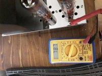
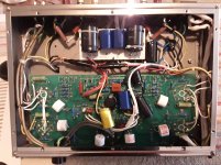
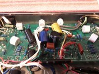
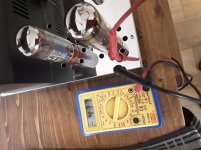
After receiving the amp I coupled it up to my mint warfedale e70s speakers and noticed the right channel was a lot lower than the left, I'm no electronic expert but had read how to bios the amp. I conected my Multimeter and set it to 2000m and connected to the valve bios test points and was shocked at the reading, 750m and counting down. The valves are a quad matched set and have a number in felt pen written on top of the el34 valves 305m. I've tried trimming the voltage down but the voltage is so unstable, I've given up. The voltage does come down after say a hour to around 150m. I removed the amp bottom cover to reveal the electronics, it's a real mess, a bodger has been inside and changed the circuit. Pictures enclosed. Sorry for the long posting.
After receiving the amp I coupled it up to my mint warfedale e70s speakers and noticed the right channel was a lot lower than the left, I'm no electronic expert but had read how to bios the amp. I conected my Multimeter and set it to 2000m and connected to the valve bios test points and was shocked at the reading, 750m and counting down. The valves are a quad matched set and have a number in felt pen written on top of the el34 valves 305m. I've tried trimming the voltage down but the voltage is so unstable, I've given up. The voltage does come down after say a hour to around 150m. I removed the amp bottom cover to reveal the electronics, it's a real mess, a bodger has been inside and changed the circuit. Pictures enclosed. Sorry for the long posting.
Attachments
Last edited:
have a look here this may be helpful My mods of Audio Institute VR-70E
aren't they cathode biased?
and if it is "variable" from the photo you've posted i don't think your red probe is in the proper location the test point is closer to the tube.
aren't they cathode biased?
and if it is "variable" from the photo you've posted i don't think your red probe is in the proper location the test point is closer to the tube.
Last edited:
Thanks for the link, interesting but way above my knowledge. Im still learning valve amps, I have recapped 2 solid state amplifiers but dont understand the voltages and cant read circuit diagrams. I dont know what you mean by cathode based.
It doesant matter whether the red+ or the black- go to earth, I still get the same results. It just shows a - minus sign on Multimeter.
can you post a photo of the control your varying in order to trim the bias?
cathode biased is fixed i.e. not on a potentiometer you must physically change resistors to affect a change in bias level.
did you notice the bias test point location? ( i don't have bitpaint to higlight the proper location in the photo)you can see the red insulation of the test point peeking out the hole a 1/2 inch north of where your probe is currently located.
Last edited:
How is it than that in the first picture in post #1 there's no minus sign on your meter, and the plus probe is in a wrong hole? The hole above it is the right one.
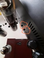
I've put another picture up with the probe's in the right place and the minus sign on the multimeter. The amp has warmed up so a lower reading showing.
Attachments
Last edited:
is this not a push-pull output?
i'd be very cautious with playing with these as you can wind up with an asymetrical waveform on your output!!
it may also come down to your (sorry to say) cheap meter's insufficient ohms/volt rating not providing a high enough impedance so as to not upset the level of the bias voltage (your meter is shunting the bias voltage).
OK, but what were you measuring in the first picture in post #1?
Addition: And now a negative reading over a resistor in the cathode lead?
Addition: And now a negative reading over a resistor in the cathode lead?
Last edited:
is this not a push-pull output?
i'd be very cautious with playing with these as you can wind up with an asymetrical waveform on your output!!
it may also come down to your (sorry to say) cheap meter's insufficient ohms/volt rating not providing a high enough impedance so as to not upset the level of the bias voltage (your meter is shunting the bias voltage).
Thanks turk, Yes I wondered if my Multimeter was upto the job, I won the meter in a compaction.Lol the amp does work fine and does sound fantastic, the valves dont appear to be red plating either. So will order a new meter. Thanks
see if you can find, beg, borrow, or bribe someone with an oscilloscope to make sure you have a symmetrical waveform when your done "tweaking" the bias controls!!!
is this not a push-pull output?
i'd be very cautious with playing with these as you can wind up with an asymetrical waveform on your output!!
it may also come down to your (sorry to say) cheap meter's insufficient ohms/volt rating not providing a high enough impedance so as to not upset the level of the bias voltage (your meter is shunting the bias voltage).
Thanks turk, Yes I wondered if my Multimeter was upto the job, I won the meter in a compaction.Lol the amp does work fine and does sound fantastic, the valves dont appear to be red plating either. So will order a new meter. Thanks
Sorry new to the forum, I'm getting confused on how to use the DIY audio forum software, so sorry if I keep posting the same post over and over again.
is this not a push-pull output?
i'd be very cautious with playing with these as you can wind up with an asymetrical waveform on your output!!
it may also come down to your (sorry to say) cheap meter's insufficient ohms/volt rating not providing a high enough impedance so as to not upset the level of the bias voltage (your meter is shunting the bias voltage).
see if you can find, beg, borrow, or bribe someone with an oscilloscope to make sure you have a symmetrical waveform when your done "tweaking" the bias controls!!!
Yes a mate of mine has a oscilloscope, but with this covid pandemic we are on semi lockdown he wouldn't be allowed in our house and I dont know how to use one. But will ask him to lend it me anyway, he will probably say no thou and I wouldn't blame him
well you would need a signal generator as well, can't check for symmetry without a clean undistorted sine wave!
A recap.
The symptom is: The volume of the right channel is a lot lower than the left channel (post #1).
Other than that, the amplifier works fine and does sound fantastic (post #13).
TS thinks it has to do with bias, so sticks the postive probe of his/her multimeter in a weird place/hole of his/her amplifier (probably making contact with the chassis, so with ground = 0 V), and the negative probe in/at an unknown place. It measures 787 mV (picture 1 in post #1).
Than TS sticks the positive probe in an appropriate place/hole, and the negative probe probabably at a place/hole where it makes contact with the chassis, and measures - 437 mV (post #8). This can't be a measurement of the voltage over a resistor in a cathode lead, because that voltage can't be negative. If it would go negative, I would either call in an exorcist or run to the patent office (or do both).
I never heard of a multimeter that gone bad, and as a result displays a negative voltage while the voltage is positive (and vice versa). But hey, what do I know...
In this context, I don't understand why some forum members advise TS to arrange for an oscilloscope and tone generator to solve the problem.
But maybe it's my lack of imagination. And anyway, to each his/her own.
Last edited:
Bios test points
Hi Robert, Dyavox have built into the vr70 amp, bios test points and have quoted bios settings around 350m for each tube. The hole that I have my meter probe in, is the makers test point and is conected to valve circuit.
and not the chassis, the other probe goes down to earth as the makers instructions.
See YouTube video.
Audio Institute VR-70E Tube Valve Amplifier failure - YouTube
In the video (I only watched, didn't hear the soundtrack), the positive probe is in an appropriate hole. The negative probe is connected to earth (= chassis). The voltage on the multimeter never goes negative, except for a short moment when the positive probe is moved to an other appropriate hole (an other EL34), but that has no meaning for the measurements.
The poster of the video is just playing with the bias adjusment, getting the measured EL34 in cut-off (zero current because of a high enough negative bias voltagte on the control grid).
This is my last posting in this thread. This thread just doesn't feel right to me. Succes with your amplifier.
The poster of the video is just playing with the bias adjusment, getting the measured EL34 in cut-off (zero current because of a high enough negative bias voltagte on the control grid).
This is my last posting in this thread. This thread just doesn't feel right to me. Succes with your amplifier.
Robert, I have now got the speaker volumes same on each speaker by using my meter and the bios ajusting pots provided in 4holes next to the valves. The voltage does settle down to around 170m after around a hour, but that's not the manufacturers recommended setting of 350m. But it does sound great. Thanks
- Home
- Live Sound
- Instruments and Amps
- Dyavox vr70 high bios voltage.