I'm posting a build I just finished. I wanted to do something different from anything I've done before, so my choices may seem a bit...unconventional.
I have a friend who's a historian and into the 1930s and 1940s. I had gifted him an old console radio years ago, but movers destroyed it. I've been keeping an eye out for something to replace it.
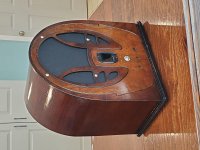
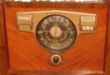
I found a Philco 89 on the 'bay. I think the old cathedral radios are some of the nicest designs from that era. The one I picked up has a cabinet in great shape - no discolorations, no missing/broken wood. A light sanding and a few coats of lacquer later and the cabinet is sorted.
The radio on the other hand...
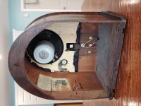
Someone had previously removed the tuning circuitry, tubes, and speaker. Since the radio couldn't go back to original, I decided to bring it up to modern utility. The insulation on the power transformer was dangerously crumbling, the resistors and capacitors were well past their useful life, and the tube sockets were baked.
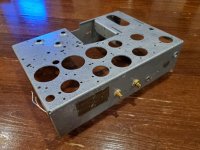
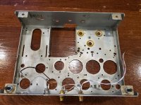
I started by stripping the chassis and giving it a coat of "hammered metalic" paint.
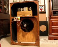
For the speakers, I had an old University 8" full range that I inherited from my grandfather. I paired that with a Dayton 3/4" Neo and a series crossover at 3000 Hz. The speakers were mounted on a 3/4" plywood subframe that was covered with speaker cloth and mounted inside the cabinet.
I have a friend who's a historian and into the 1930s and 1940s. I had gifted him an old console radio years ago, but movers destroyed it. I've been keeping an eye out for something to replace it.
I found a Philco 89 on the 'bay. I think the old cathedral radios are some of the nicest designs from that era. The one I picked up has a cabinet in great shape - no discolorations, no missing/broken wood. A light sanding and a few coats of lacquer later and the cabinet is sorted.
The radio on the other hand...
Someone had previously removed the tuning circuitry, tubes, and speaker. Since the radio couldn't go back to original, I decided to bring it up to modern utility. The insulation on the power transformer was dangerously crumbling, the resistors and capacitors were well past their useful life, and the tube sockets were baked.
I started by stripping the chassis and giving it a coat of "hammered metalic" paint.
For the speakers, I had an old University 8" full range that I inherited from my grandfather. I paired that with a Dayton 3/4" Neo and a series crossover at 3000 Hz. The speakers were mounted on a 3/4" plywood subframe that was covered with speaker cloth and mounted inside the cabinet.
Attachments
Last edited:
Was a field coil speaker OEM? AlNiCo is a post WW2 development.
I doubt it matters? He said the original speaker was 'previously removed'; the woofer now is 'an old University 8" ...from my grandfather'.
However there's a nifty rundown of the Philco 89 here; long production run for the time but seems to be all field coil.
After repairing 1000,s of old tube radios I can assure you that the reason "energized " field coil speakers were used was that very old speakers had them was because of the low flux density of the voice coil magnets which greatly improved as time went on.
It also saved money from adding a power supply choke to the price of a production line .
I have an extension speaker that used this method , lovely piece of woodwork ,later extension speakers just needed two wires with a volume control in series with one wire.
I am glad to see someone rebuilding an early radio --called wireless in the UK.
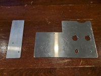
Unfortunately, all the tuning components (variable capacitor, tuning coils, dials, knobs) were missing. I think someone before my tried to rebuild but gave up. Replacement parts are un-obtaninium. So basically this is going to become a conventional amp/speaker combo so a regular line source can drive it.
To keep things safe, I needed to blank out the extra holes. Something like this should work.
To keep things safe, I needed to blank out the extra holes. Something like this should work.
Attachments
You just "broke my heart " Fenris a beautiful antique wooden radio case being turned into a practice amp .
Why not sell the case to a US antique radio enthusiast I know plenty of them ?
Yours is the 1935 model ( shown June 1934 ) -- check out this USA website for parts and history-
Evolution of Philco Model 89 – Philco Library
Just think of the enjoyment on hearing it working after completion.
Why not sell the case to a US antique radio enthusiast I know plenty of them ?
Yours is the 1935 model ( shown June 1934 ) -- check out this USA website for parts and history-
Evolution of Philco Model 89 – Philco Library
Just think of the enjoyment on hearing it working after completion.
Last edited:
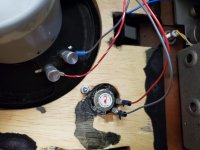
For the B+ I went with one of the cheap 12v to 220v inverters from ebay. It's "rated" at 150 watts, so I'm guessing 40 watts reliably. I usually go with a MOSFET series regulator, but I decided to do a passive filter. The higher frequency makes the filter components smaller and the frequency is probably above audibility.
The power for the amp comes from a 12v switchmode power supply. The 12 comes in and is switched by a relay to keep the current through the ON/OFF switch to a minimum. The 12v is run to a bus block as a central location for the 12v. The heaters will use this for power.
I also figured I'd use a small fan to keep everything cool, so I put in a RC filter in front of it. This serves two purposes - it reduces the voltage to the fan, making it spin slow enough to be inaudible. Also, since modern brushless fans are really just fancy power modulators, it reduces any EMF noise produced by the fan from leaking back into the main 12v supply.
For the B+ I went with a CRCLC filter. PSUD and LtSpice tell me it's theoretically going to have millivolt ripple, so that should be good enough.
Attachments
Unfortunately, all the tuning components (variable capacitor, tuning coils, dials, knobs) were missing. I think someone before my tried to rebuild but gave up. Replacement parts are un-obtaninium. So basically this is going to become a conventional amp/speaker combo so a regular line source can drive it.
To keep things safe, I needed to blank out the extra holes. Something like this should work.
It may be possible to rebuild it as an AM radio. This item would work for the tuning capacitor. AES has a suitable local oscillator coil. Get IF transformers here. Superhet schematics are "a dime a dozen". Inexpensive Loctal types could make up most, if not all, of the tube complement.
Last edited:
For the tubes, I went with one of my favorites: the 6GV8 / ECL85 / 6F5P. It has plenty of NOS availability around the world, very linear curves, and has a triode and pentode in a single bottle that only uses .9 amps for the heater.
Starting with power section, I went with a very standard autobias grounded cathode push pull arrangement. The output transformer is an Antek power torroid with two 7v secondaries in parallel. That should give a 8000 or so ohm inductance on the primary. The 6GV8s are triode strapped. Looking at the datasheet, with 220v of B+, 40ma of current results in 20v of bias needed. I used a 560 ohm resistor on the cathode because I had a bunch of 5w resistors in stock. It's bypassed with a 63v 560uf Elna cap with a .1uf film cap in parallel. This needs about +/- 20v to drive it and will produce a few watts, which is all I need.
Starting with power section, I went with a very standard autobias grounded cathode push pull arrangement. The output transformer is an Antek power torroid with two 7v secondaries in parallel. That should give a 8000 or so ohm inductance on the primary. The 6GV8s are triode strapped. Looking at the datasheet, with 220v of B+, 40ma of current results in 20v of bias needed. I used a 560 ohm resistor on the cathode because I had a bunch of 5w resistors in stock. It's bypassed with a 63v 560uf Elna cap with a .1uf film cap in parallel. This needs about +/- 20v to drive it and will produce a few watts, which is all I need.
Attachments
Putting modern components inside an old cabinet can be a wonderful thing.
I started with a large 1947 Philco console that had AM, FM, Shortwave. It had a 78 changer, and two 12 inch full range.
The problem was, the owner only had room for one radio or stereo.
The desire was to play those modern things (33 Stereo LPs), and to play them in stereo.
A new record changer, tuner, stereo amplifier, and a 2 way 'left channel' speaker was inserted into the cabinet.
A bookshelf had the 'right channel' speaker put on a bookshelf.
It sounded great, and satisfied the owner.
There are 2 groups of people . . .
Some want the old 1928 Hup-mobile,
Some want a V8, auto transmission, and radial tires, and a complete new suspension installed into the Hup-mobile.
. . . To each his own.
Just sayin'
The driver section is going to be more complex. It would be easy enough to go with a voltage gain stage and then a concertina phase splitter, but I've done that before. Instead I decided to try an AC coupled long tail pair. To make a CCS for the tail, I used a LM134 set with a 22 ohm resistor at 4.5ma. But this needs at least 3-4v across it to have enough headroom to work. The triode will normally be biased at about 1v, so this will be a problem unless I can find a way around it (which I can).
One of the things I had to deal with was the extra holes in the chassis. There are four holes up front, so I used one for a power switch and one for volume. To fill up the other two I decided on using tone controls.
The triode of the 6GV8 models fairly well as a 12AT7, not exact, but good enough for testing things in Spice. To get the +/- 20v of drive that I need would be easy, except a tone control loses about 8db of signal and should ideally be driven from a low impedance source. With a tone control in place, there wouldn't be enough drive from a standard +/- 1v line level signal. So, I had to get creative.
Attachments
You just "broke my heart " Fenris a beautiful antique wooden radio case being turned into a practice amp .
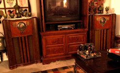
I made a nice pair of stereo speakers out of a matched pair of 1941 vintage Zenith consoles, one actually worked.......but I did save the original field coil speakers, baffle boards, and Wavemagnets (rotating antennas), and all other components that would be needed to return the radios to as found condition, the other radio did not work, but had a tasty pair of 6V6G tubes that played in my 6V6 SSE amp for a while, but got kicked out of their sockets by some grey glass RCA's, so they're back in the old radio.
These cabinets now house a pair of 15 inch Hawthorne Silver Iris coaxial drivers rated at 96 db SPL@1 watt. They are absolutely deadly when fed with a 125 WPC tube amp at full crank...open up the windows and go outside and mow the lawn without hearing the mower kinda deadly!
The CRT TV and the VHS machine tell you that this happened quite some time ago, about 15 years. The radios are still rocking the house, and all the parts are still stored in a safe place, but I don't see returning the radios to originality any time soon. Note the globe tubes (NX-483's) in the Lexan TSE on the table they are from 1929 and still crank out about 2 WPC on a bit more B+ than they are rated for.
Attachments

Last edited:
For some, the old looks might be appealing enough to overcome that dreaded effect . . .
WAF.
And coming from me (I hate acronyms). So . . .
Wife Acceptance Factor.
WAF.
And coming from me (I hate acronyms). So . . .
Wife Acceptance Factor.
This is for a friend. He doesn't and probably never will listen to AM radio (and there is a dearth of quality programming on AM from what I've experienced). This Philco was a basket case requiring complete replacement of...everything...except the chassis. Swapping out the radio components for something more practical and modern seemed to be the best solution.
You did the most prudent thing to make it useful
I find a 12Ax7 into ksc3503 concertina works really well
I find a 12Ax7 into ksc3503 concertina works really well
When FETS were introduced way back in time communications guys made use of them to replace tubes in communications receivers with them using plugin bases .
Higher current versions made use of Mosfets --I have circuits for both , but think on would you tell a "dyed in the wool " tube enthusiast who swoons over the "smoothness" of tubes to replace that very expensive and near "unobtainum" tube with a mosfet ?
I doubt it --thats how I feel about original old antique radios and there are people on DIY Audio who have carefully renovated very old amplifiers with 1920,s tubes and are proud of their work as they have preserved an electronic component that is part of the History of early electronic engineering.
Surface is surface but its inside something or somebody that really counts.
If all you have is a cabinet and a chassis, all you need is lots of time on your hands, and lots of money, to restore it to original.
Correct,
The surface of an object or of person is one thing.
The inside of an object or of person is another thing.
But a person who took the time and effort to give a gift that is specially focused on the person who receives the gift,
that counts for a lot (even if it is not a restoration).
Correct,
The surface of an object or of person is one thing.
The inside of an object or of person is another thing.
But a person who took the time and effort to give a gift that is specially focused on the person who receives the gift,
that counts for a lot (even if it is not a restoration).
Last edited:
The Philco cabinet has four holes on the front. Two were taken up by the power switch and volume. So I have two holes to cover up.
I decided that I should add a tone control. First, it takes up two holes, and second, it might help adjust the sound since the open back will be very sensitive to placement.
A tone control typically reduces the signal by about 8db, so I'm going to need to make up that gain. I didn't want to add another tube for such low gain. Fortunately, I have a 12v supply nearby and a stack of Toshiba 2SK170s that I picked up a decade ago. For those who don't know JFETs, think of them as a small triode. JFET J3 is biased by R17 and R21. In addition, R17 provides some feedback. R23 and R16 set the gain, which with the feedback ends up being 3. Unfortunately, this also allows about 90% of power supply noise to be injected into the signal. J4 is a source follower. J2 functions as a constant current source. Normally the source and gate would be tied to ground, but I wanted to cancel out any power supply noise. C12 and R1 form a RC high pass filter at about 7Hz that feeds 100% of the power supply noise to the gate. R22 is 10% of J2's internal resistance, this gives 90% of opposite current conduction.
The output feeds both the grid of one of triodes in the long tailed pair. This provides both signal and a nice DC offset that lifts the grid up to about 8v DC and provides plenty of headroom for the CCS.
It also feeds the tone stack. The tone stack provide a signal to the other triode in the long tailed pair, just at a lower level, basically feedback. The tone controls work backward though. Overall this is about the right level of gain.
Attachments
For some, the old looks might be appealing enough to overcome that dreaded effect . . .WAF.
That's exactly how this project came to be. Most....no, all of my speaker cabinet creations range from not WAF approved, to flat out fugly.
One day we were wandering through an "antique flea market" when she spotted the first dead Zenith radio. She said why can't you make speakers that look like that. Well the answer is obvious, many of my creations were of "pine boards and sheetrock screws" quality, but the light bulb in my head lit up so brightly that it blinded me.
The old radio went into the back of the station wagon and followed us home. The next day I set out to find something that looked similar, and Ebay led me to an identical radio a few miles from my house. I made arrangements to go see it, and unfortunately there was music playing on the radio when I got there, that makes the price go up, but it was still cheaper than making something like it from scratch.
A few days later these were sitting in the living room blasting out some Pink Floyd. 15 years and two moves totaling 1200 miles later they're still there although the ancient TV, VCR and wall unit in between them have been replaced by an Xbox, a 65 inch flat screen and a (fake) fireplace.
- Home
- Amplifiers
- Tubes / Valves
- Rebuilding an old Philco 89