Hi Guys, I started to build an amplifier similar to EAR 859 but without any negative reaction and after the test the results are excellent, practicaly at anoutput power of 15w THD are 3% THD and 12w the distorsions are less than 1,6% measured with analog devices but also with the ARTA program. The harmonic distribution up to 10w is close to that of an SE amplifier with 300b whics is encouraging and if possible please someone skilled in simulations to check these results if necessary i can provide adiditional data, thanck you
Attachments

Member
Joined 2009
Paid Member
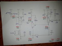
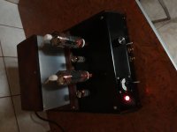
Looks nice (I stood on my head to read the upside down schematic!); don't see many screen driven amps. Any photos of what you built ?
On the second page, third column, of this article about the EAR 859, it is explained that the first stage has a gain of 150 to be able to drive the power stage correctly.
In your schematic the first stage has a gain of about 24 and the second stage, being a cathode-follower, has a gain of close to 1 (the same like in the EAR 859).
There is GNFB going on in the EAR 859 so some of the gain is being lost in the process. However, in the article it says that the amount of GNFB is minimal.
So it looks like your amplifier has less gain than the EAR 859. How dit you get the results you measured? What was the input voltage for the measured output power of 15 Watt? Can you provide a complete schematic, and with measured voltages?
Attachments
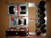
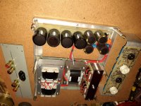
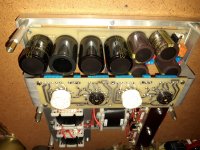
This is the complete diagram of the amplifier and some photos with it under construction, the output transformers are almost finished, core with oriented grains and a section of 19 cm square
Attachments

Last edited:

The voltage between the cathode and the anode of the second stage is 230 - 57 = 173 V.
Vg of the second stage is 48 - 57 = - 9 V.
Looking at the datasheet for the ECC88, a section would pass no current at Va =173 V and Vg = - 9 V.
Are you sure your measurements are correct?
Vg of the second stage is 48 - 57 = - 9 V.
Looking at the datasheet for the ECC88, a section would pass no current at Va =173 V and Vg = - 9 V.
Are you sure your measurements are correct?
The measurments are from the initial tests, after starting the amplifier i will measure again, it may be an erroneous value, your observation is correct
You really didn't manage to adjust your photos right? It is, err, somewhat annoying to have them downloaded first and reopen them in another application, just to see them correctly.
Best regards!
Best regards!
Marius, How did you choose the 6.4K impedance for the output transformer?
Thanks, S.
Chefparton, I'd like a copy of the documentation if you wouldn't mind sending me a PM.
Thanks, S.
Thanks, S.
Chefparton, I'd like a copy of the documentation if you wouldn't mind sending me a PM.
Thanks, S.
- Home
- Amplifiers
- Tubes / Valves
- Variant EAR 859